| Report reference number: 39844 | According to: IEC TS 62446-3 |
| Inspection date and time: Sunday 2024/02/18 11:45 | Report creation date: Sunday 2024/02/25 00:00 |
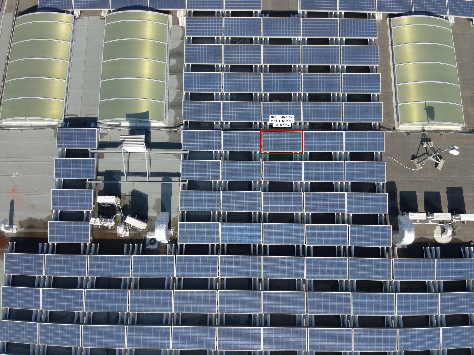
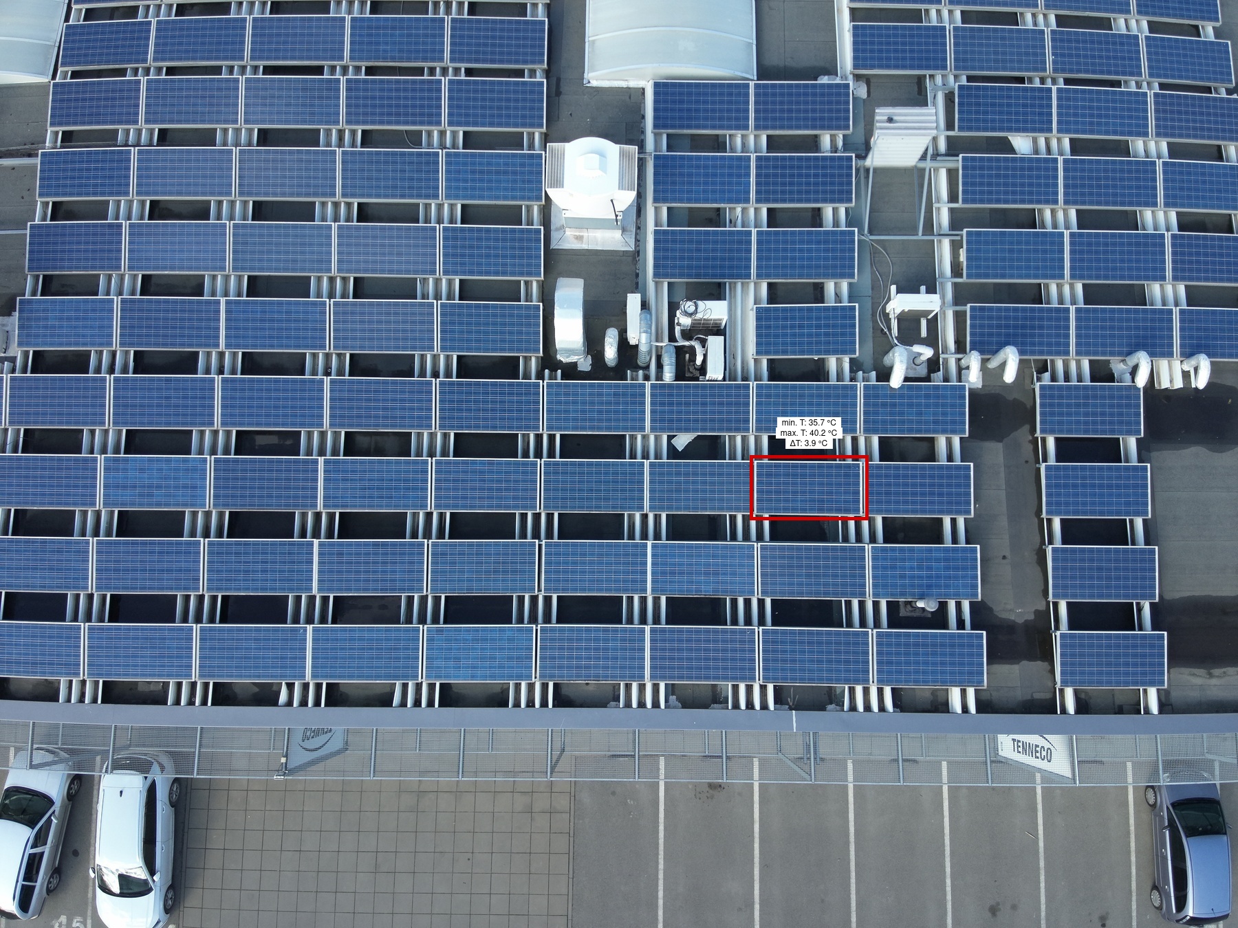
| Inspection site: FVE na průmyslových halách | |
| Address: Brno | GPS coordinates: 49.1950602, 16.6068371 |
| Site owner |
|
|---|
| Client |
|
|---|
| Inspection processor |
|
|---|
| Power plant |
|
|---|
| Data collection |
|
|---|
| Weather |
|
||||||
|---|---|---|---|---|---|---|---|
| Inspection |
|
|---|
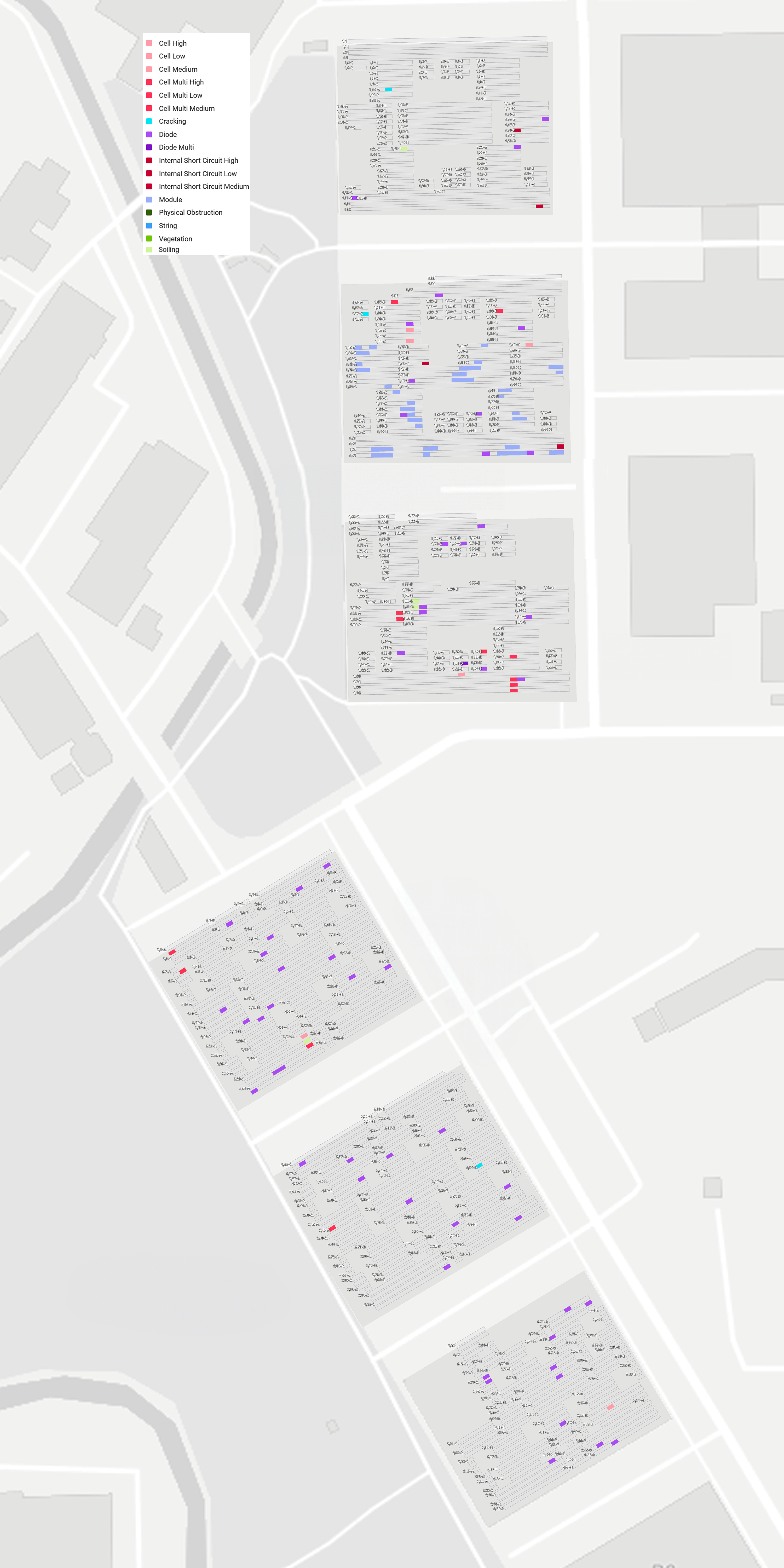
The following anomalies were found on the panels of the inspected photovoltaic power plant, with a total of 140 on 140 modules.
The total estimated annual power loss is 27 230,00 kWh.
| Anomaly name | Number of anomalies *(1) | Number of modules *(2) | Estimated power loss (kW) *(3) | Estimated power loss (%) *(4) | Estimated annual power loss (kWh) *(5) | Estimated annual financial loss (CZK) *(6) |
|---|---|---|---|---|---|---|
|
Cell Low |
5 | 5 | 0,52 kW | 0,06 % | 520,00 kWh | 2 080,00 CZK |
|
Cell Medium |
1 | 1 | 0,10 kW | 0,01 % | 100,00 kWh | 400,00 CZK |
|
Cell Multi High |
1 | 1 | 0,16 kW | 0,02 % | 160,00 kWh | 640,00 CZK |
|
Cell Multi Low |
9 | 9 | 1,42 kW | 0,15 % | 1 420,00 kWh | 5 680,00 CZK |
|
Cell Multi Medium |
3 | 3 | 0,47 kW | 0,05 % | 470,00 kWh | 1 880,00 CZK |
|
Cracking |
3 | 3 | 0,95 kW | 0,10 % | 950,00 kWh | 3 800,00 CZK |
|
Diode |
57 | 57 | 5,98 kW | 0,63 % | 5 980,00 kWh | 23 920,00 CZK |
|
Diode Multi |
1 | 1 | 0,21 kW | 0,02 % | 210,00 kWh | 840,00 CZK |
|
Internal Short Circuit High |
3 | 3 | 0,31 kW | 0,03 % | 310,00 kWh | 1 240,00 CZK |
|
Internal Short Circuit Low |
1 | 1 | 0,10 kW | 0,01 % | 100,00 kWh | 400,00 CZK |
|
Module |
52 | 52 | 16,38 kW | 1,73 % | 16 380,00 kWh | 65 520,00 CZK |
|
Soiling |
4 | 4 | 0,63 kW | 0,07 % | 630,00 kWh | 2 520,00 CZK |
| Total | 140 | 140 | 27,23 kW | 2,88 % | 27 230,00 kWh | 108 920,00 CZK |
*(1) Anomaly: Number of occurrences of a given anomaly type.
*(2) Modules: Number of modules affected by the given anomaly type.
*(3) Estimated Power Loss (kW): The estimated power loss is defined as the product of the number of affected modules, the plant’s peak power (STC), and the anomaly-specific performance impact factor (on a scale from 0 to 1).
*(4) Estimated Power Loss (%): The estimated power loss expressed as the ratio of the lost power to the plant’s total capacity, shown in percentage terms.
*(5) Estimated Annual Power Loss (kWh): The estimated annual energy loss in kilowatt-hours, calculated as the power loss multiplied by the number of solar hours per year.
*(6) Estimated Annual Financial Loss (CZK): The estimated annual financial loss is calculated based on the annual energy loss in kilowatt-hours multiplied by the price per kilowatt-hour. The price per kilowatt-hour is determined according to the feed-in tariff provided by the client for the purpose of this calculation.
For more information about individual anomaly types, please refer to the end of this document.
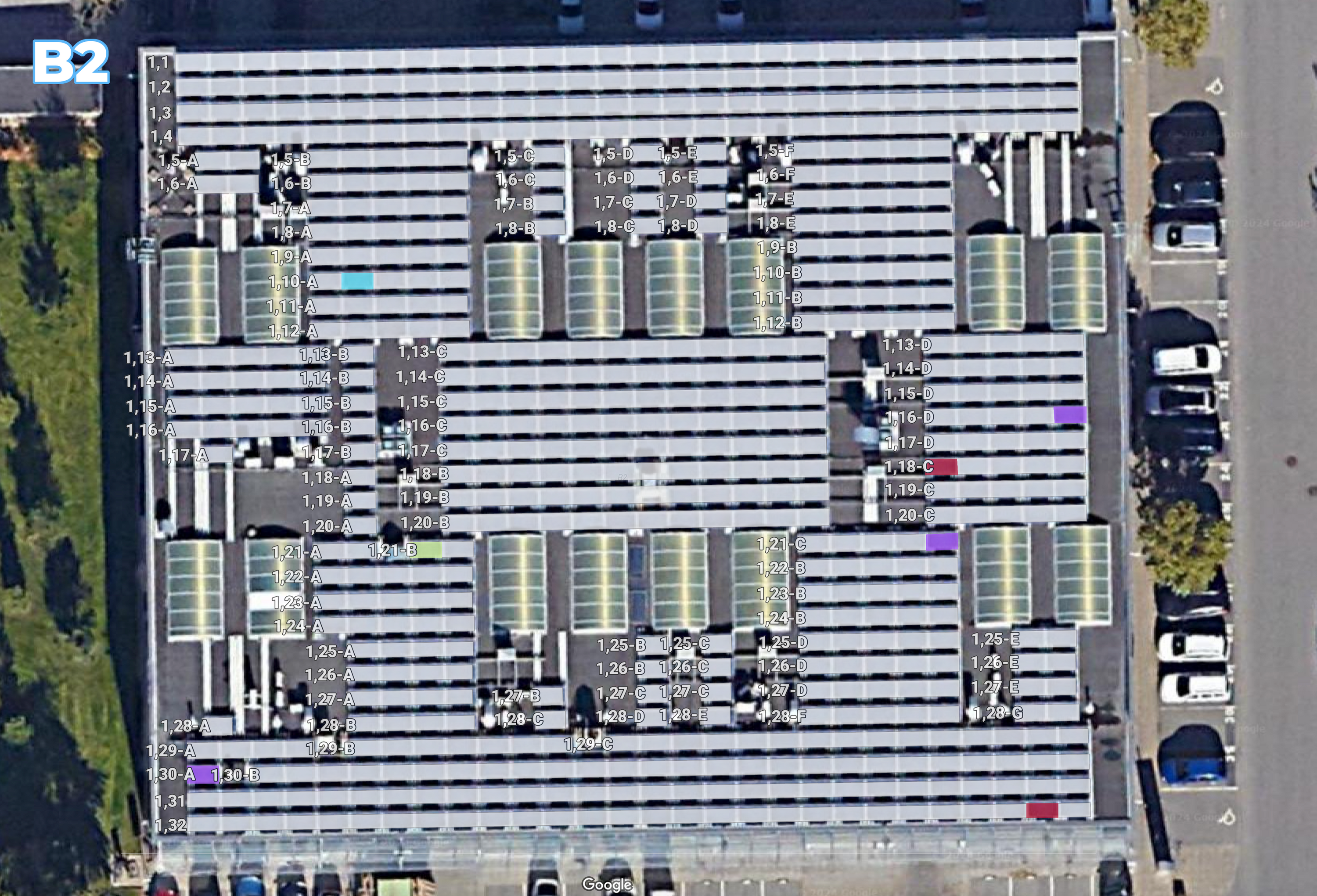
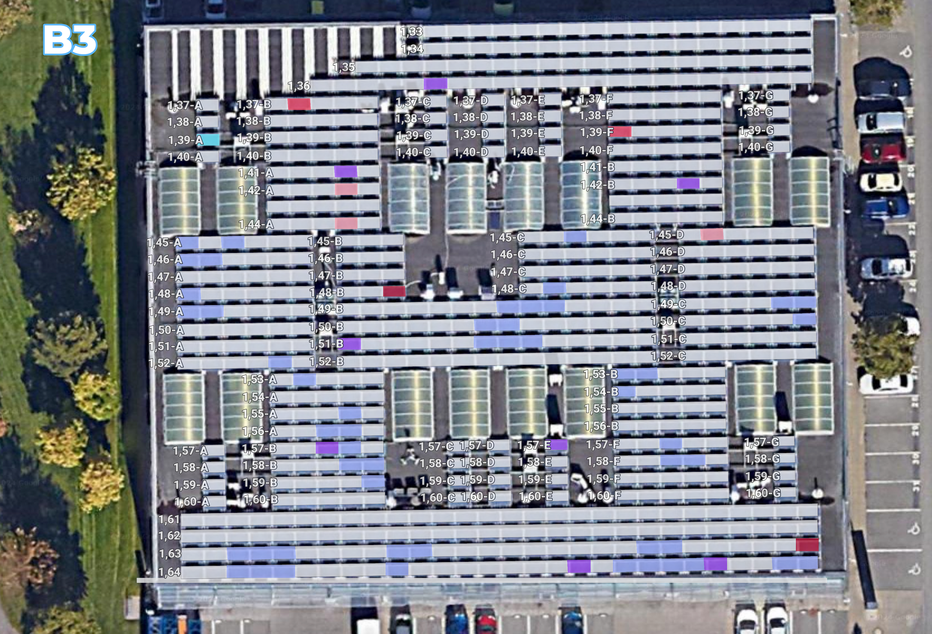
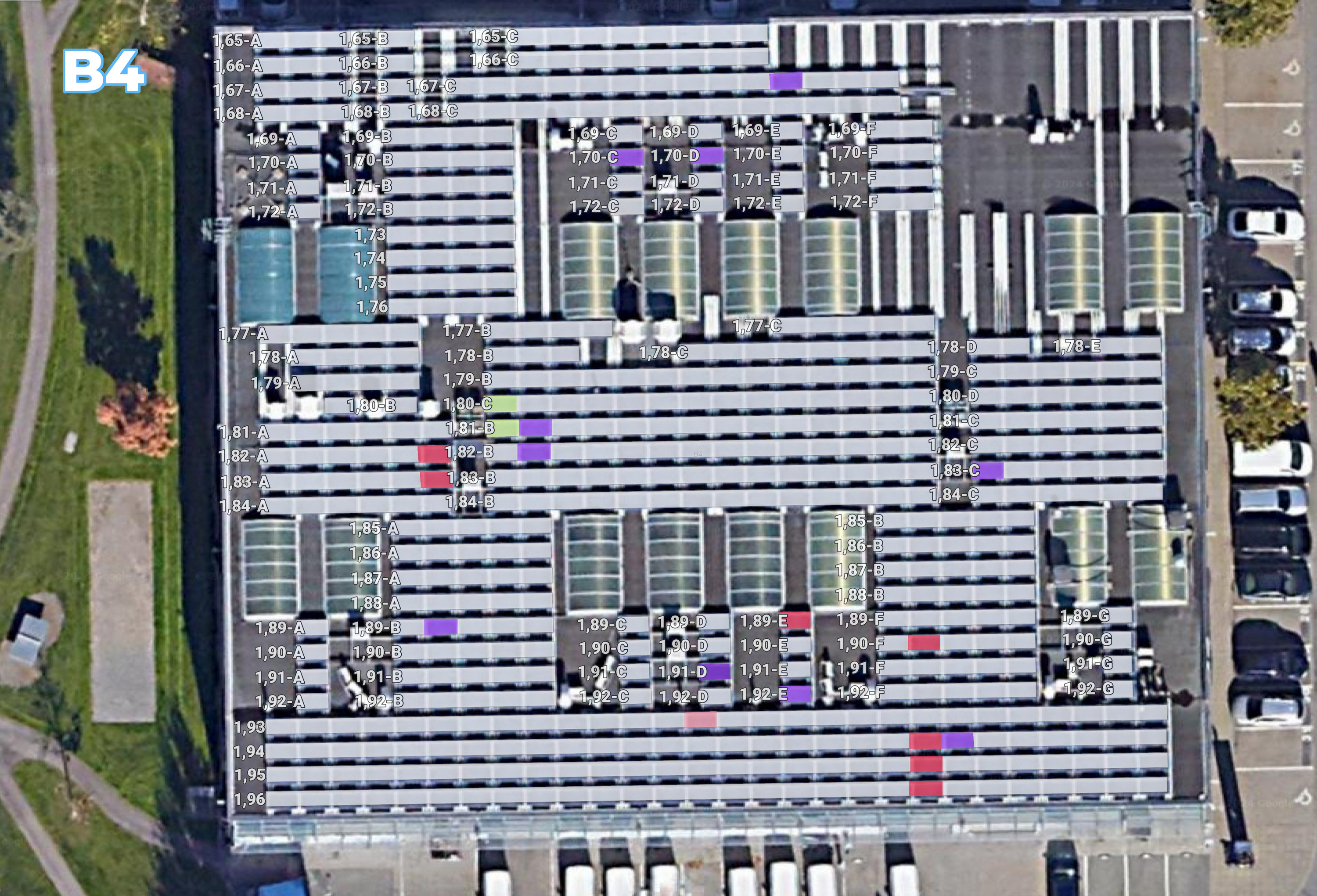
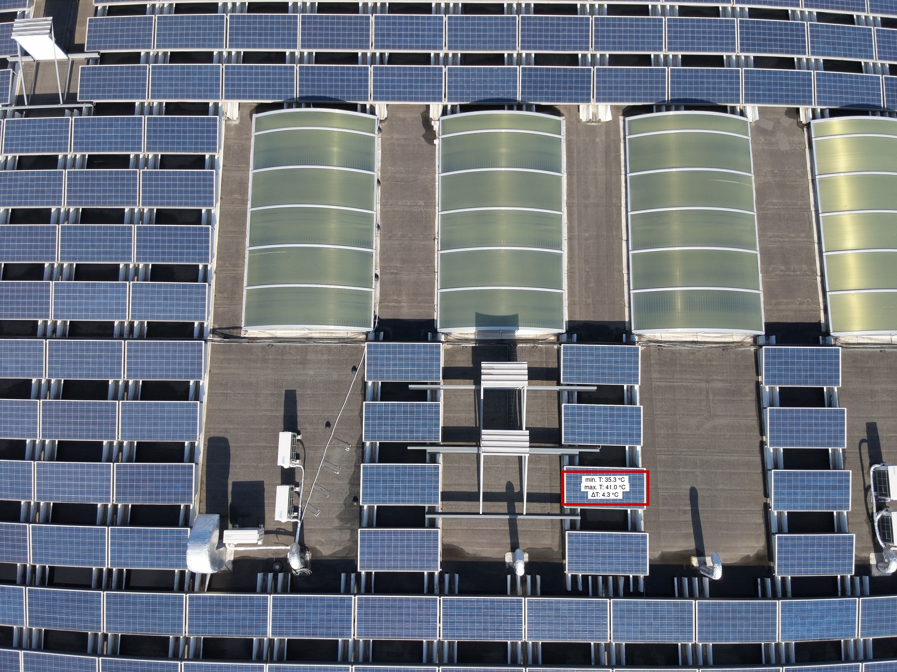
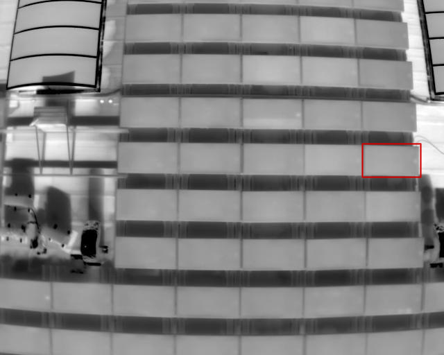
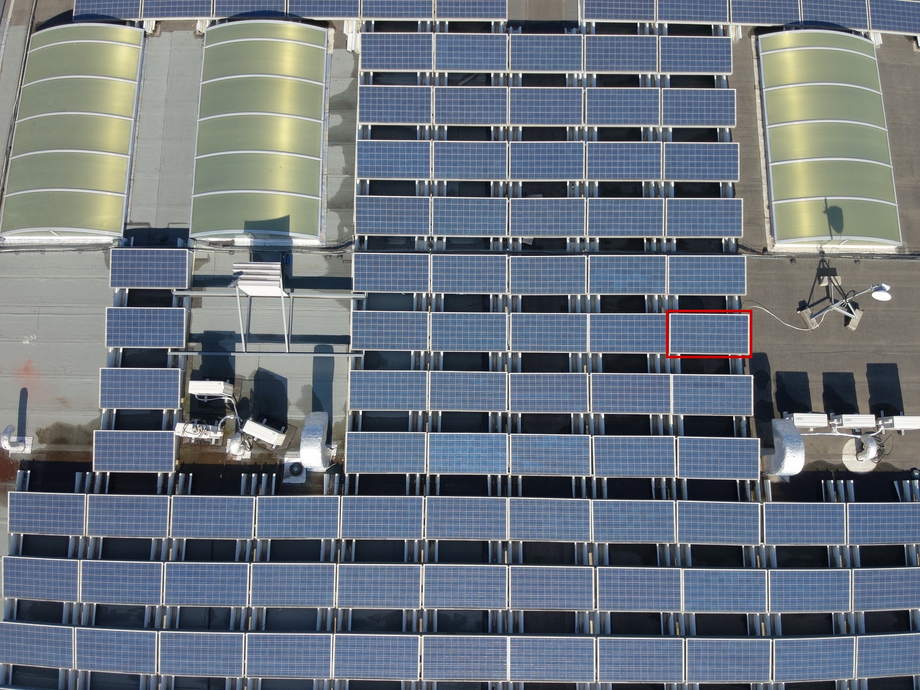
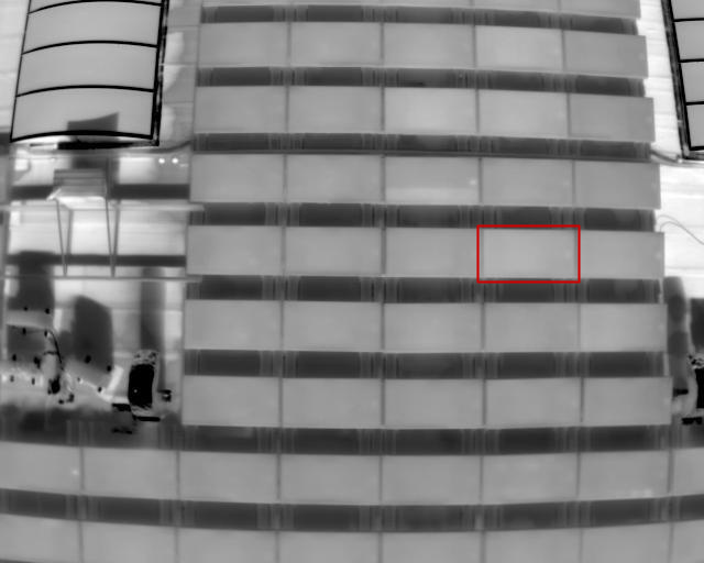
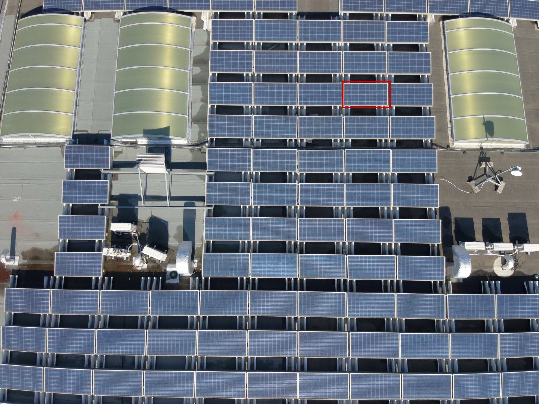
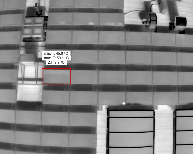
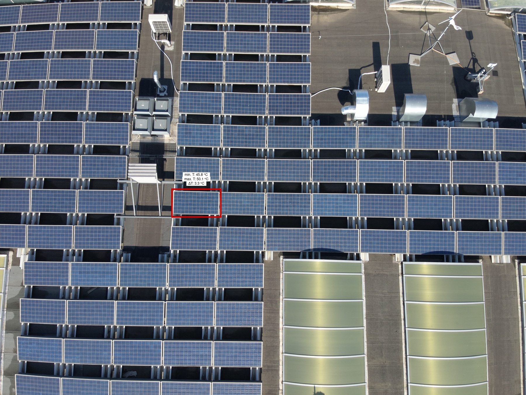
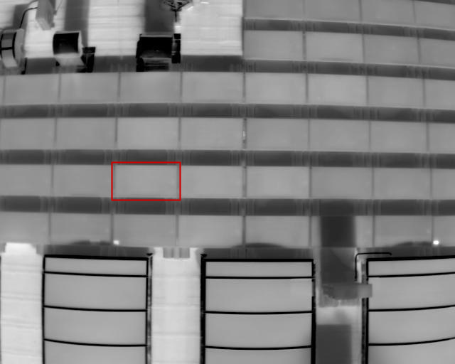
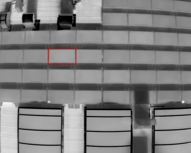
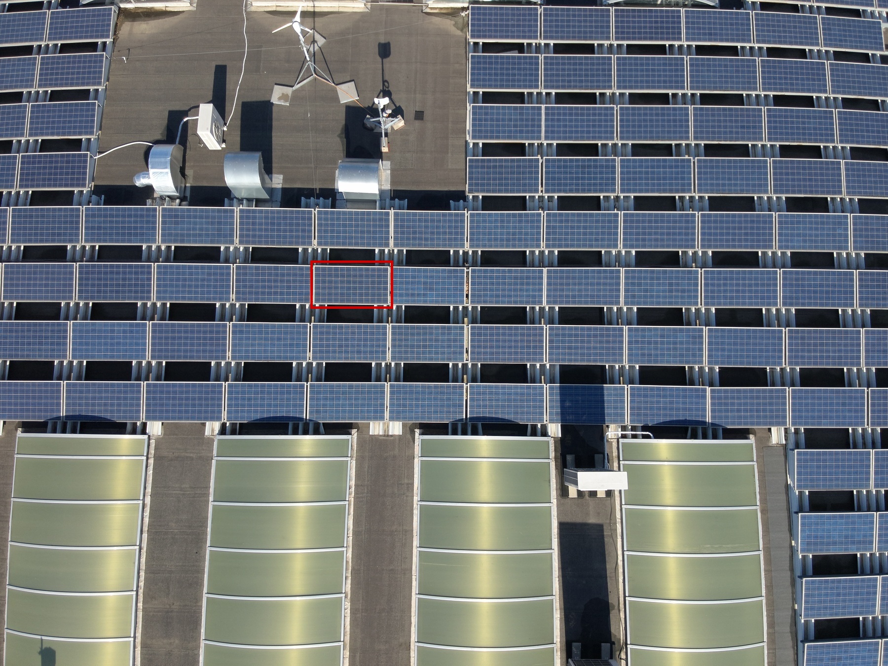
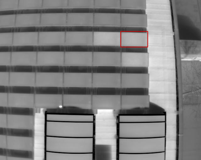
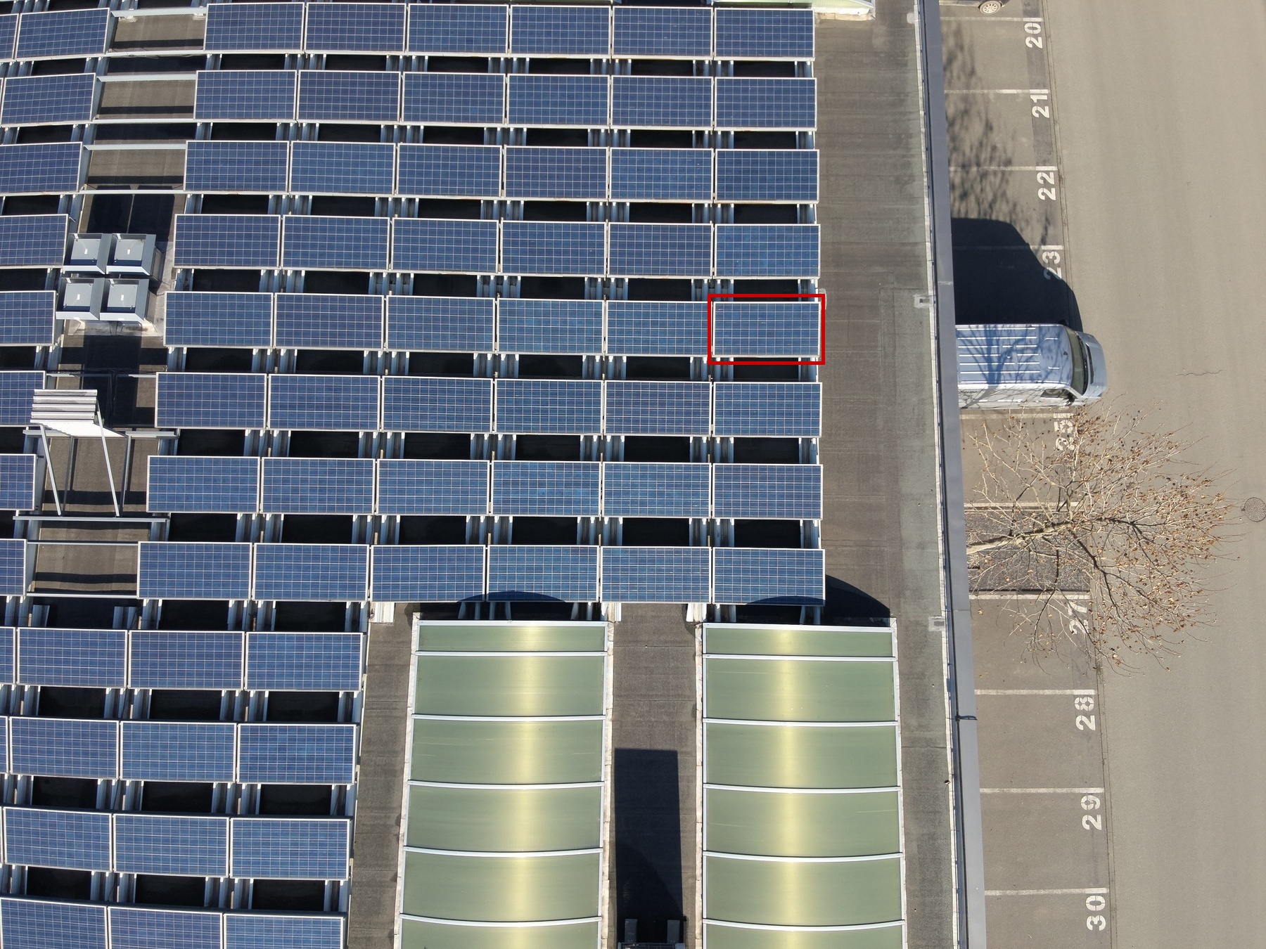
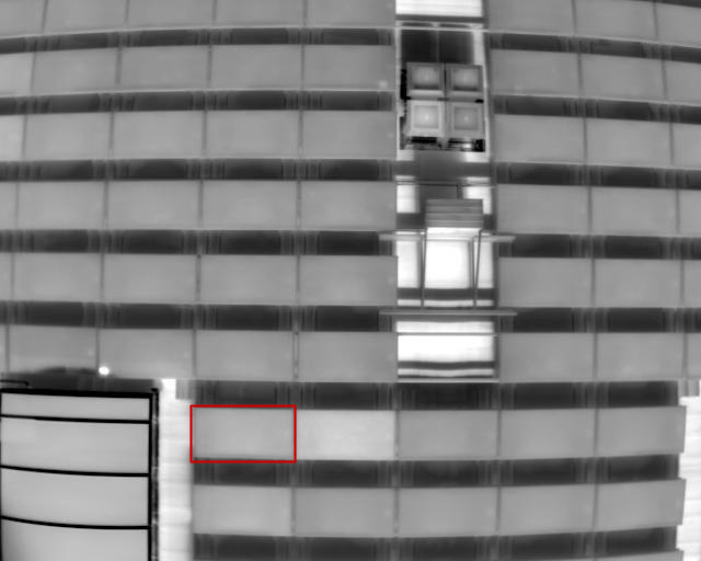
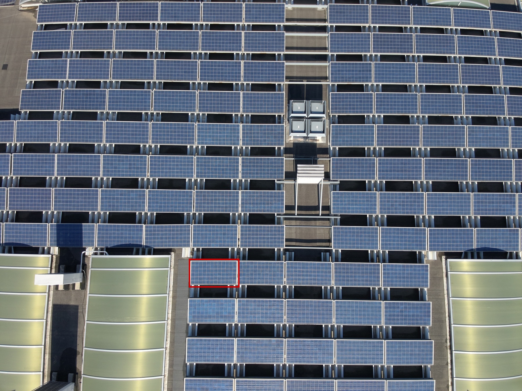
| Primární fotka | Sekundární fotka | Anomaly name | Row X | Row Y | String X | String Y | Module X | Module Y | Priority | Delta T | Proposed next action |
|---|---|---|---|---|---|---|---|---|---|---|---|
|
|
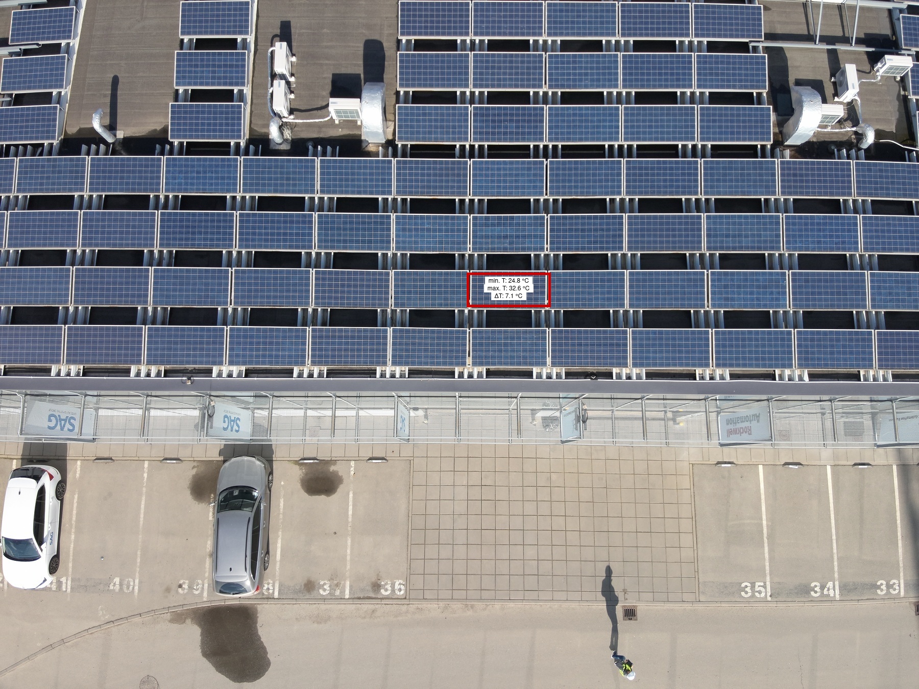
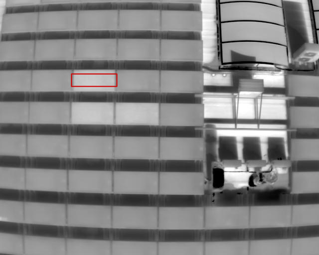
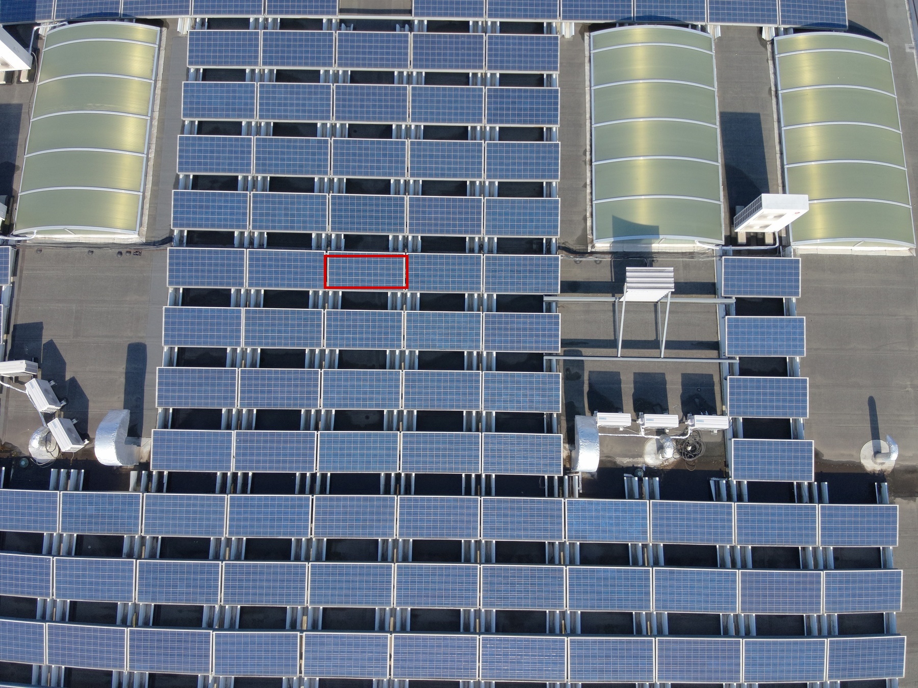
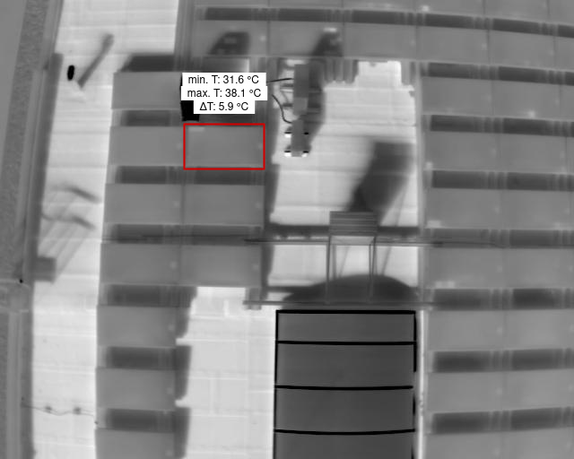
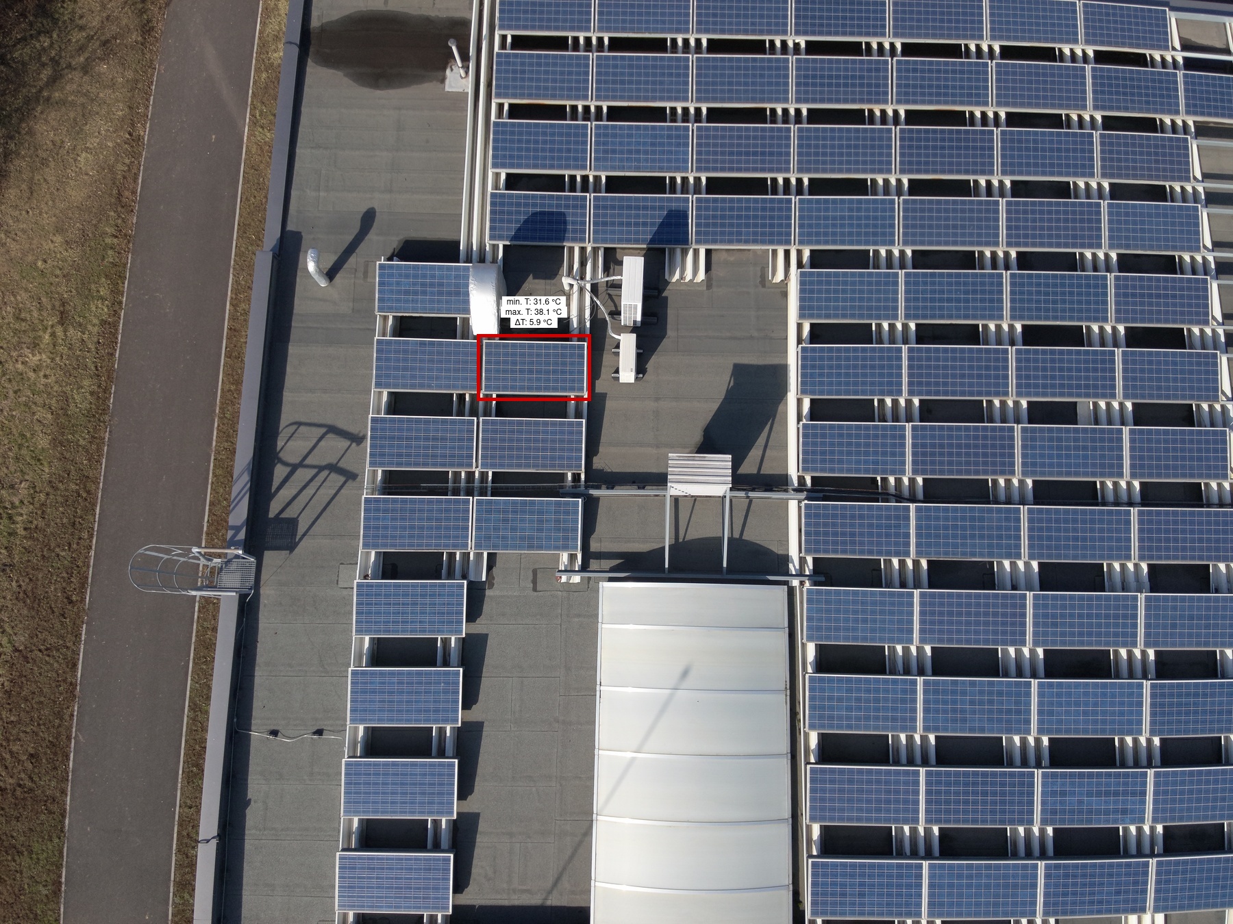
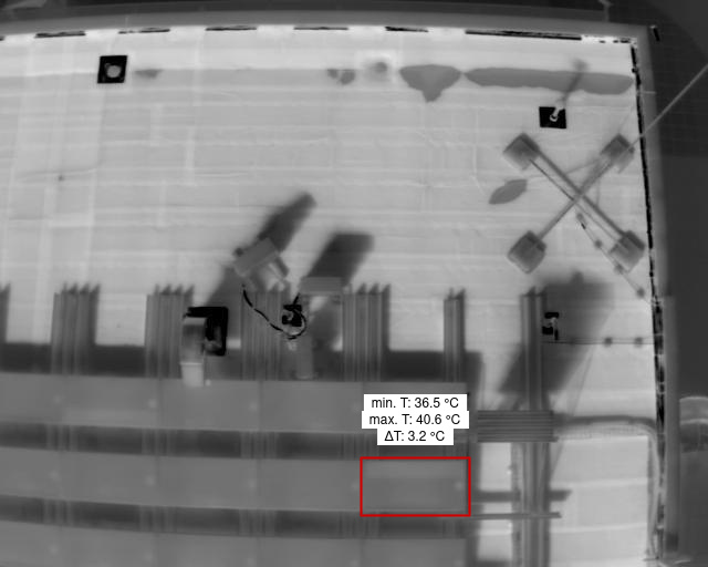
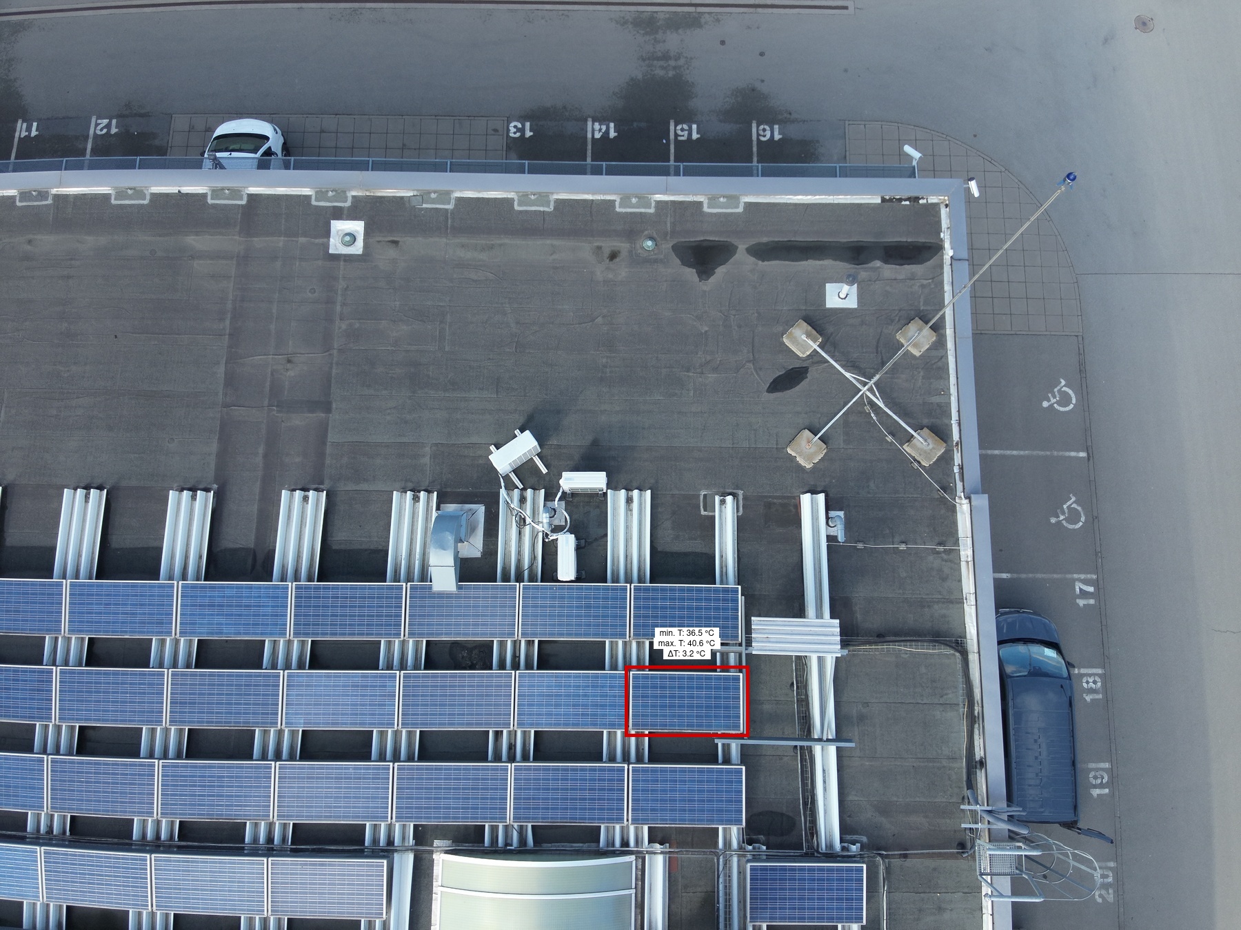
Cell Multi Low |
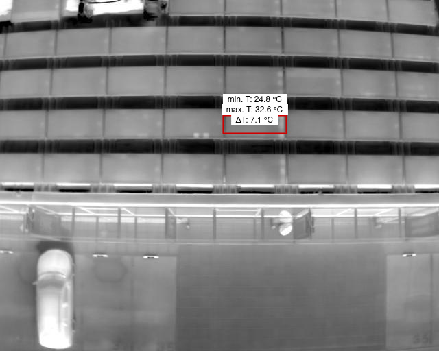
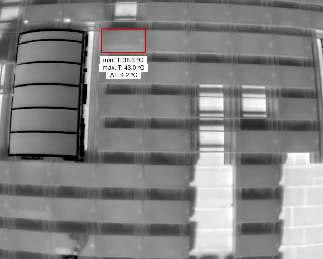
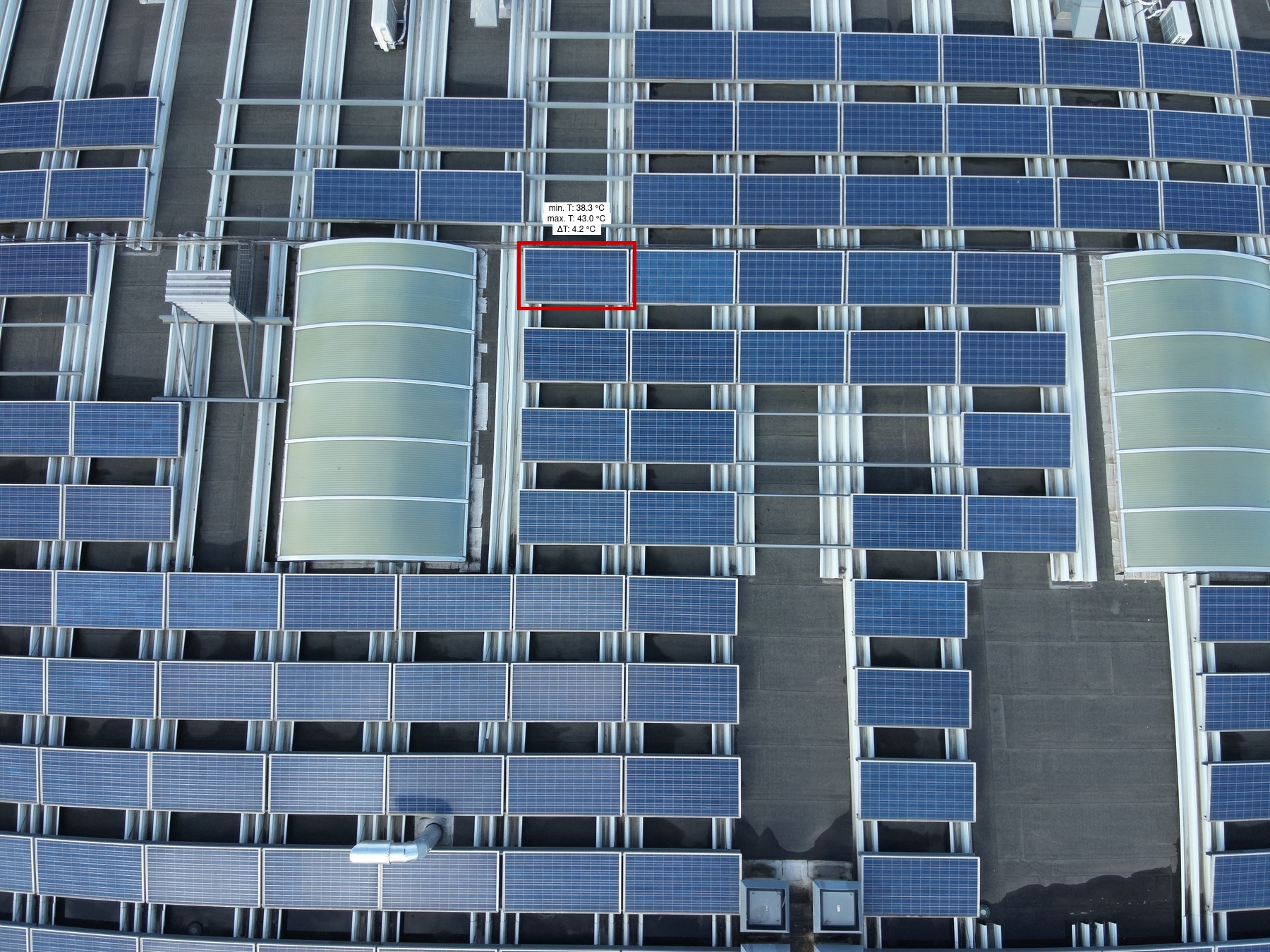
1 | 95 | 1 | 1 | 21 | 1 | Low | 7.1 | |
|
|
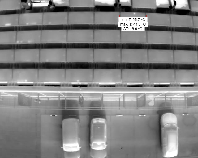
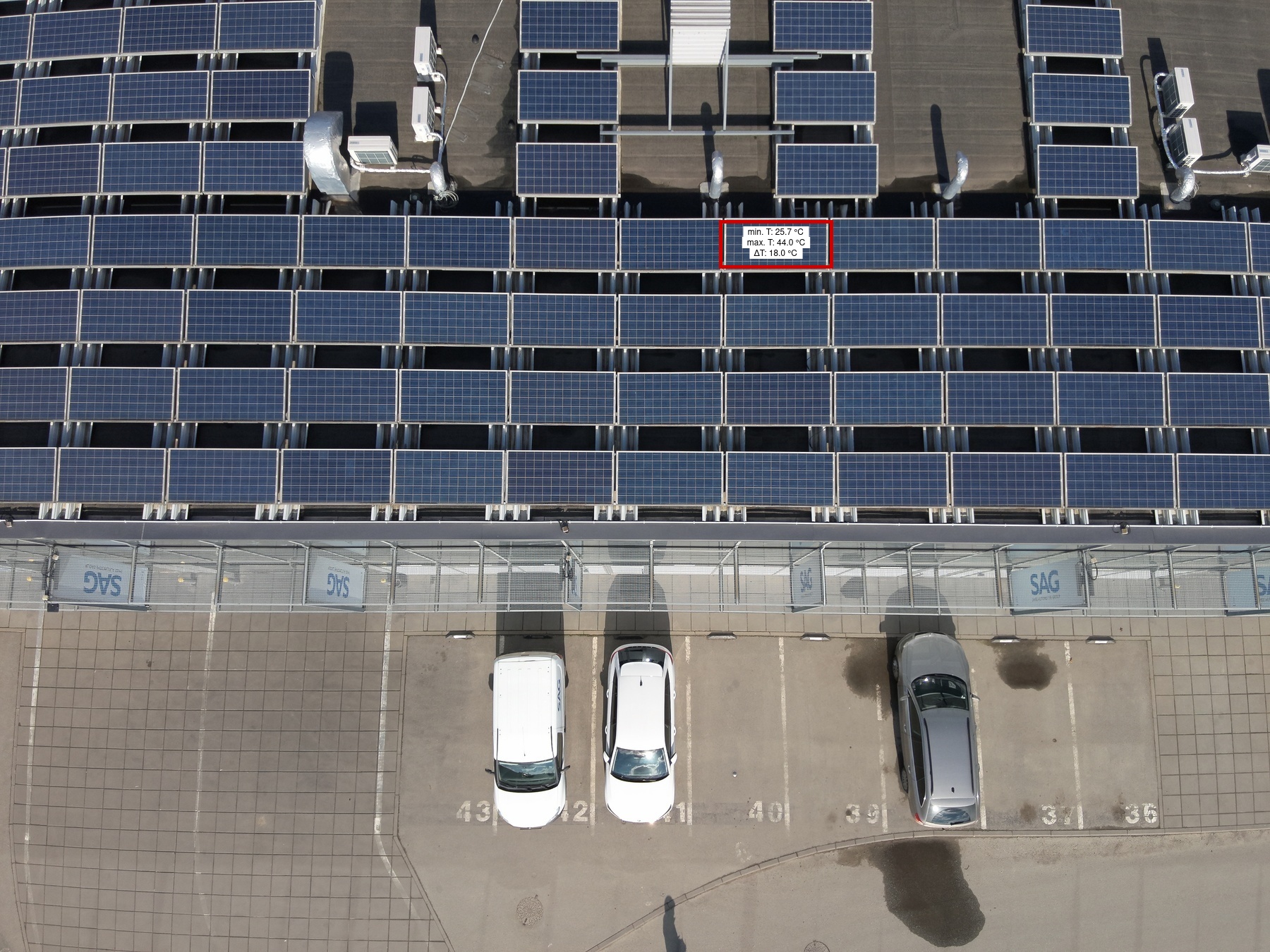
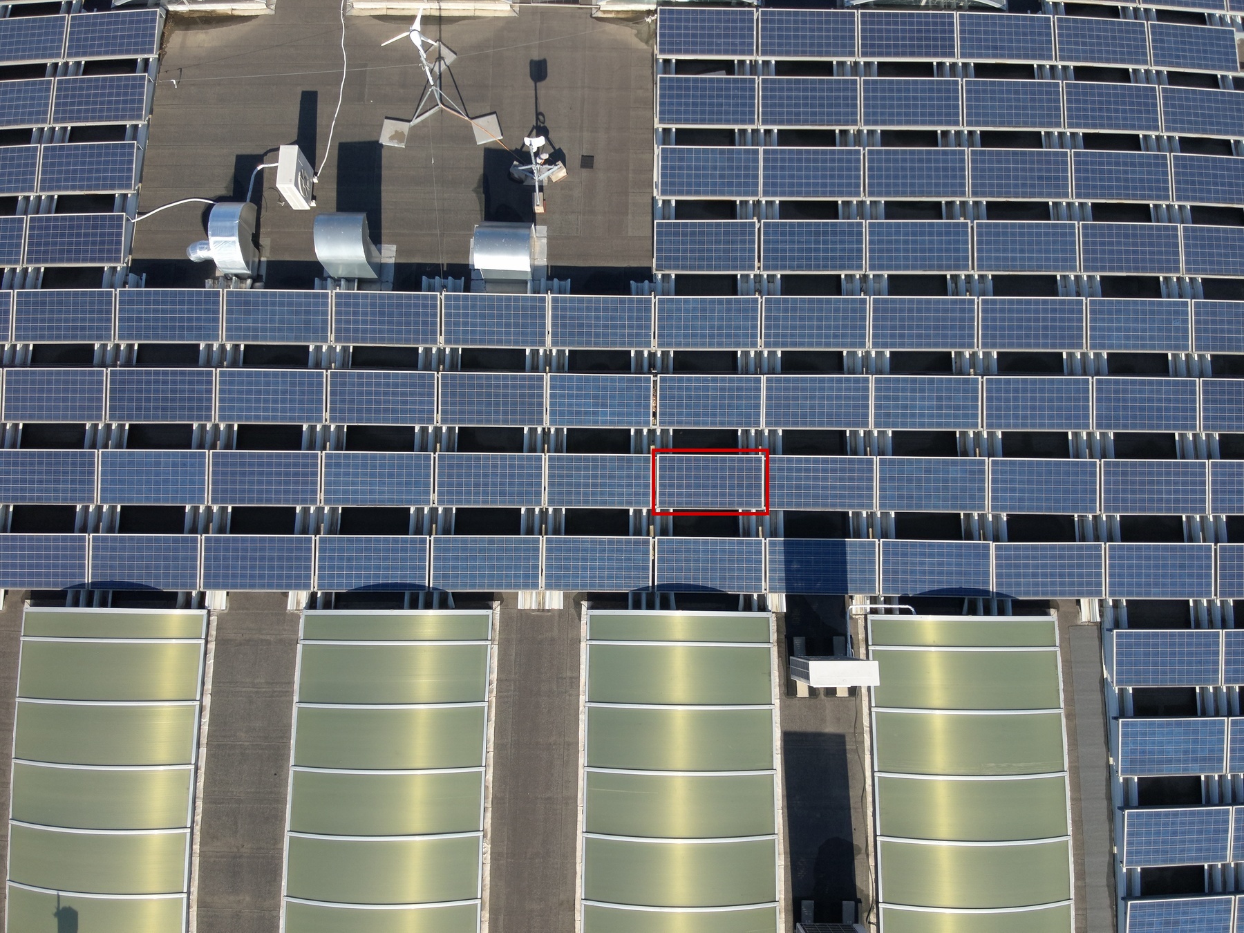
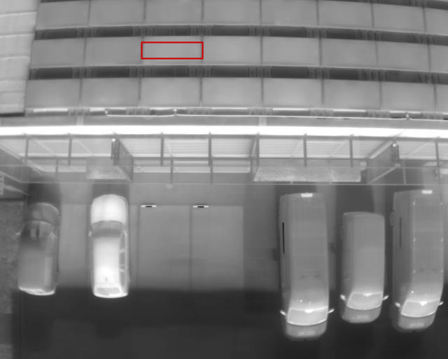
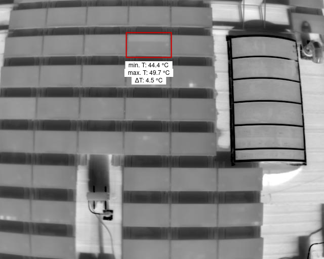
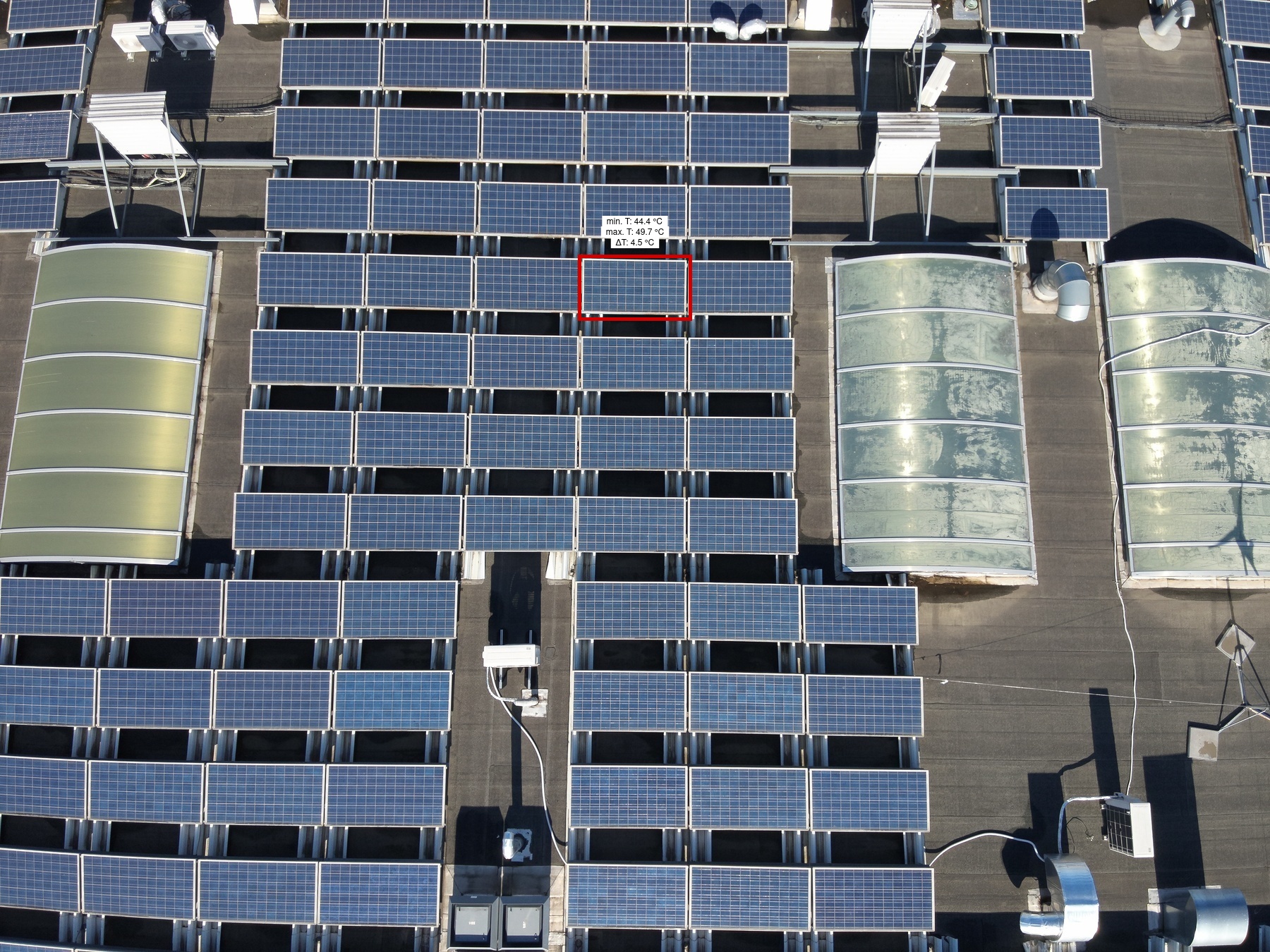
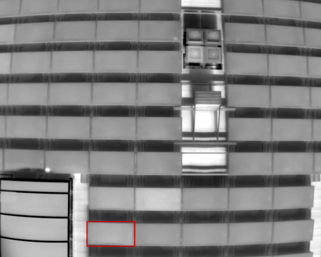
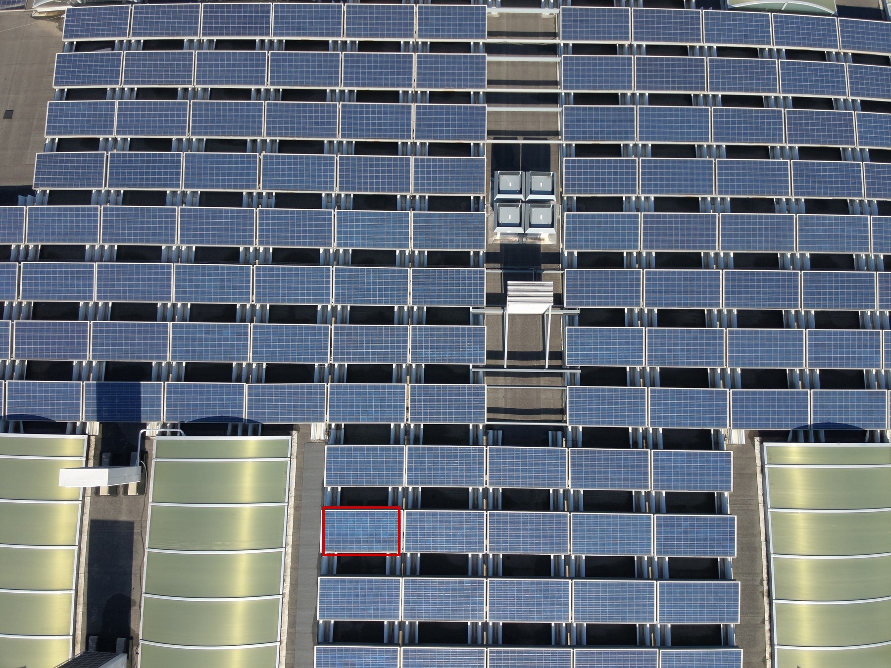
Cell Medium |
1 | 93 | 1 | 1 | 14 | 1 | Low | 18 | |
|

|
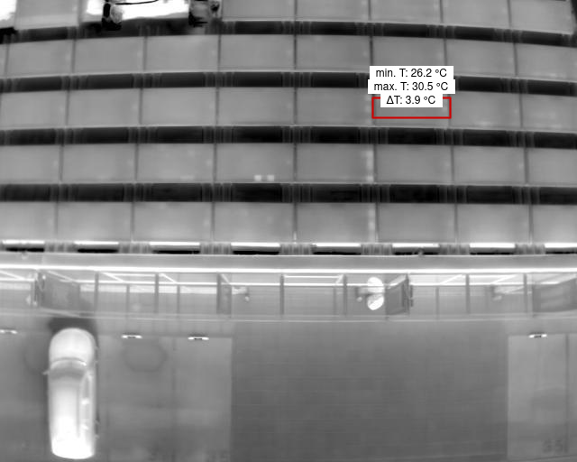
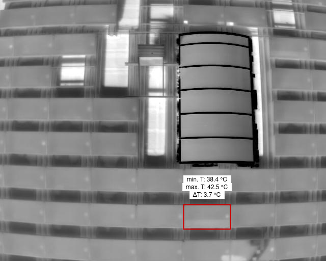
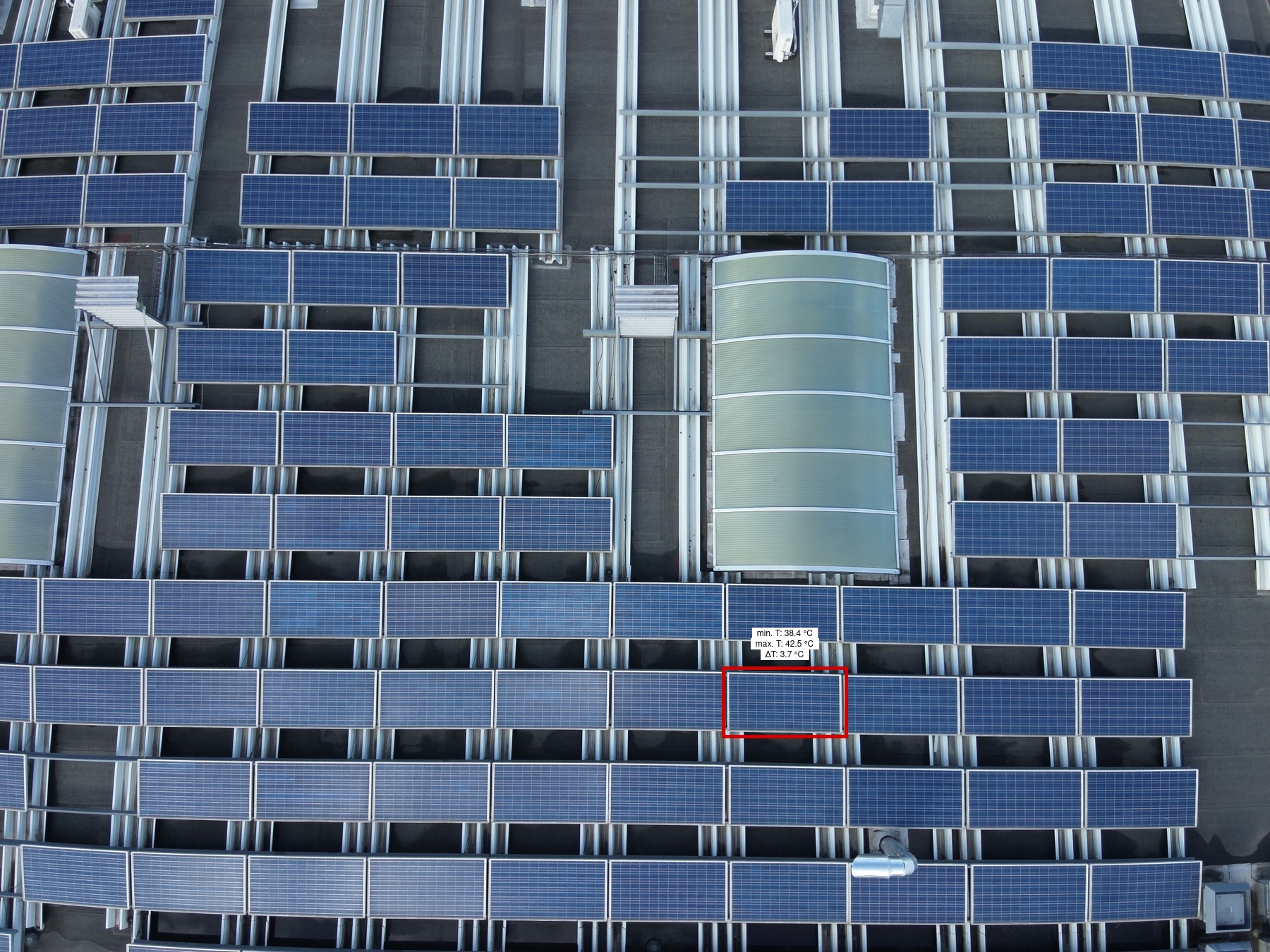
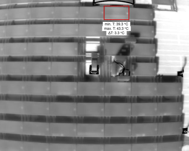
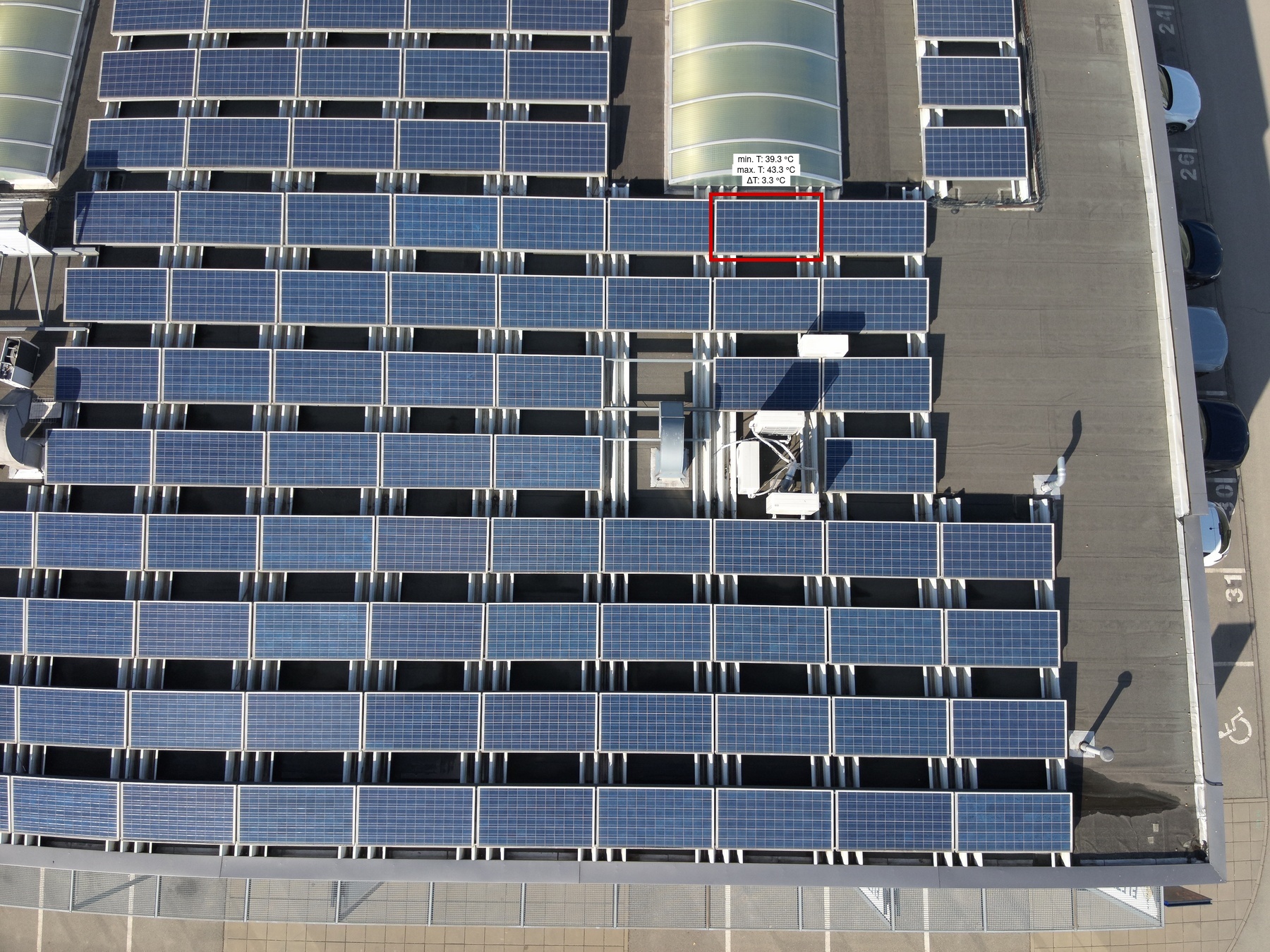
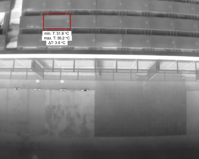
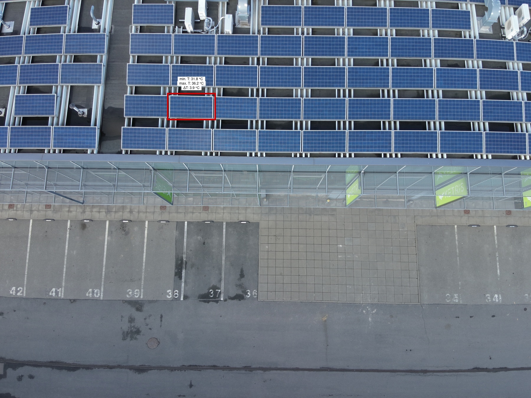
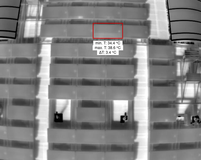
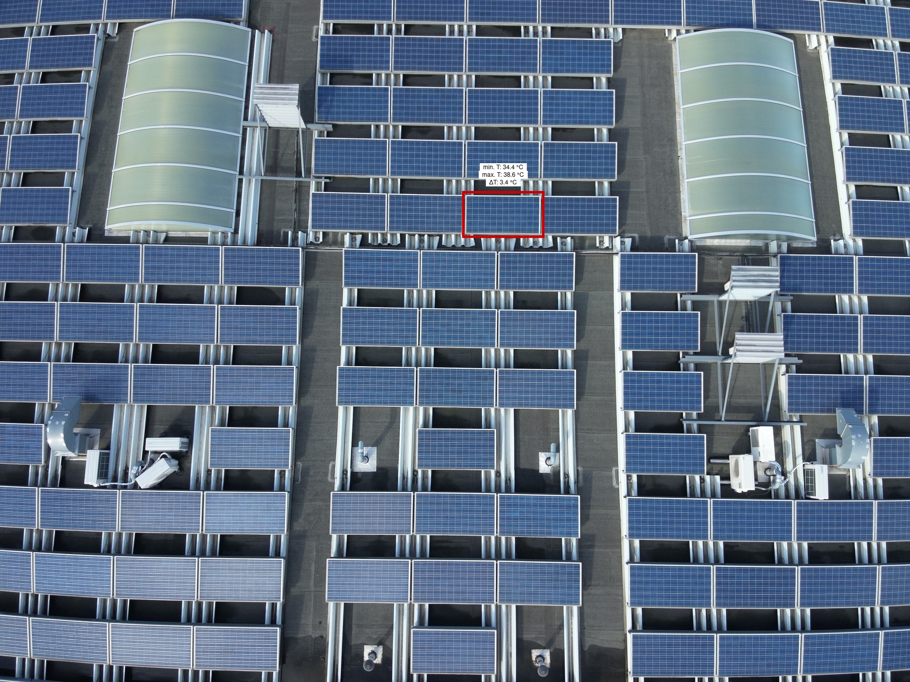
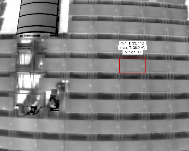
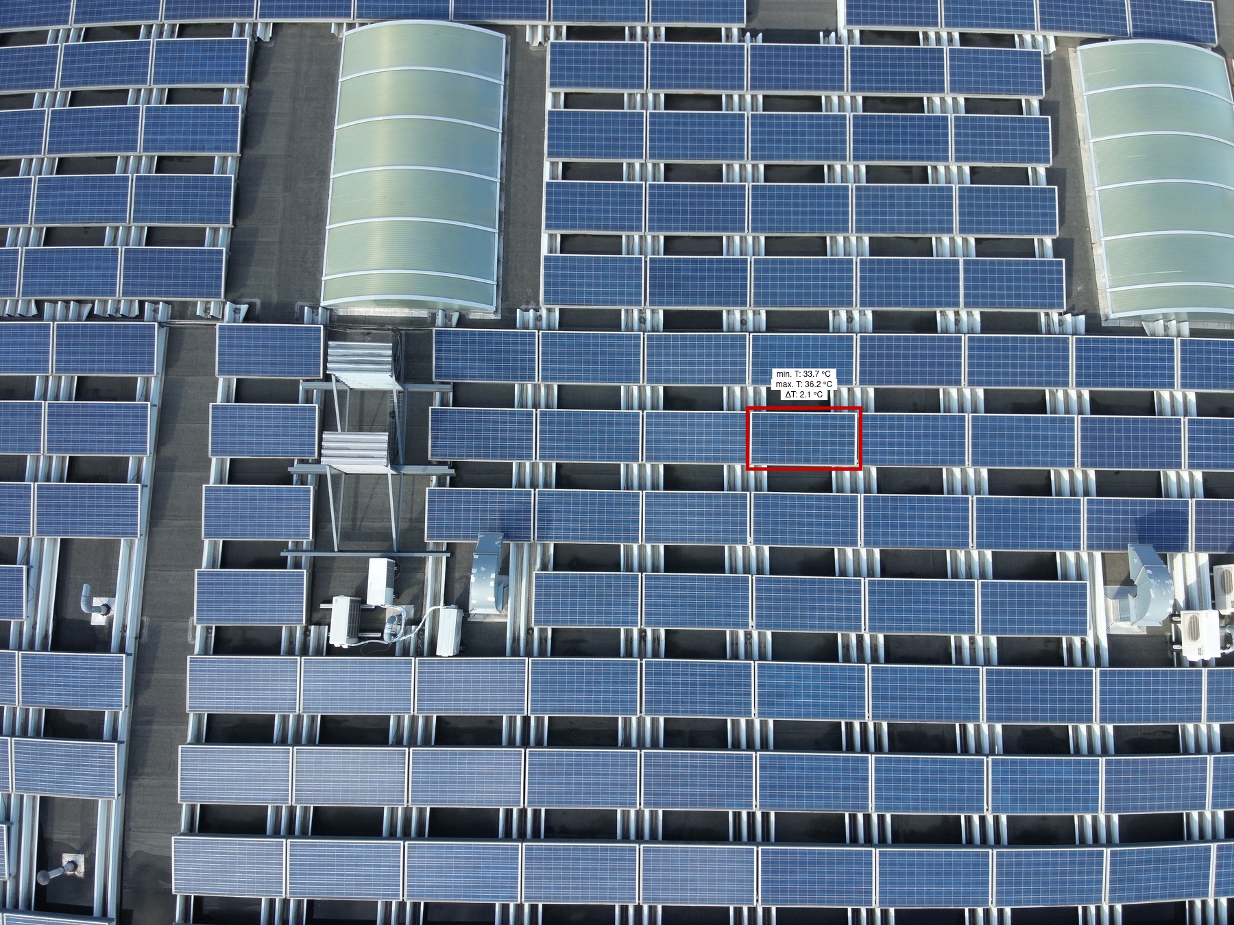
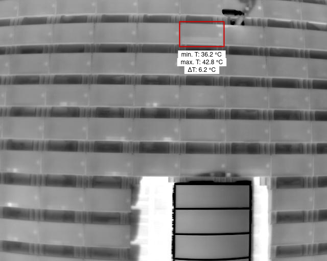
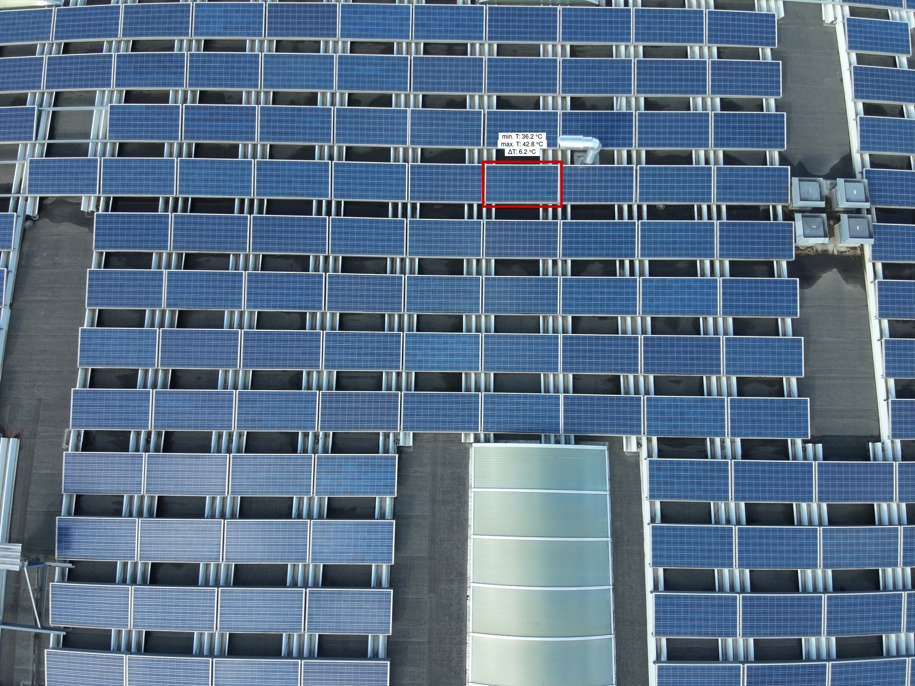
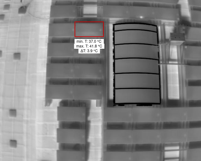
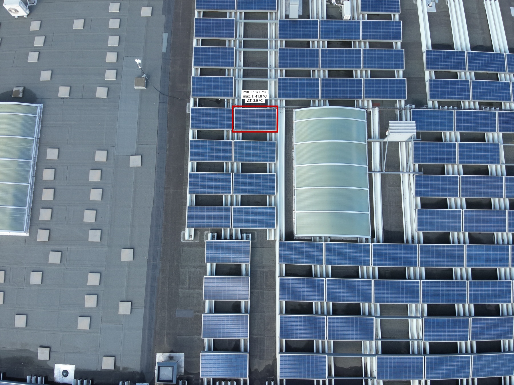
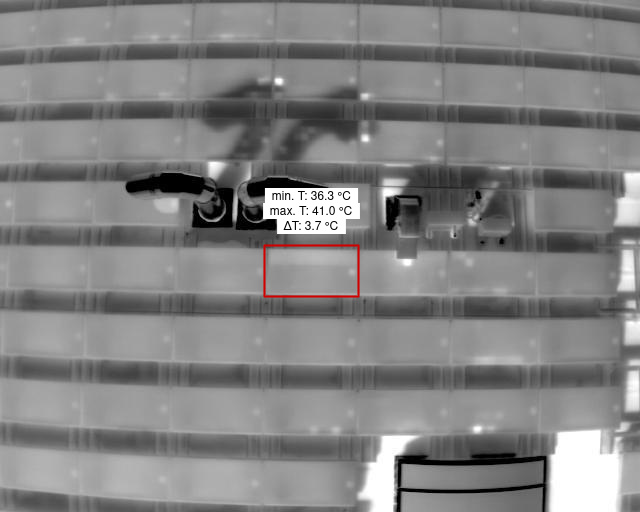
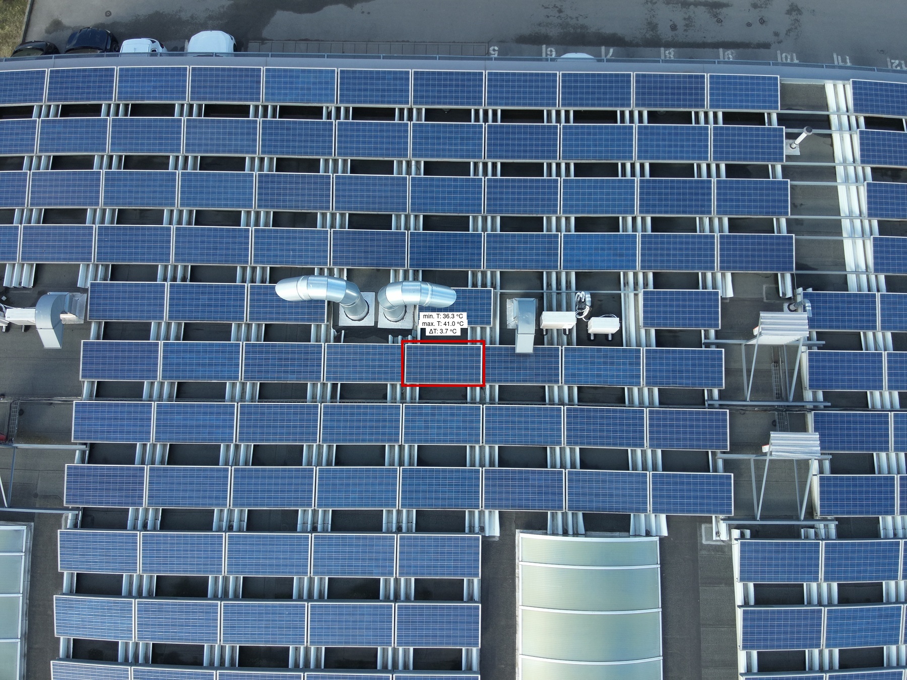
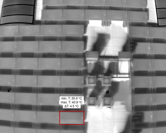
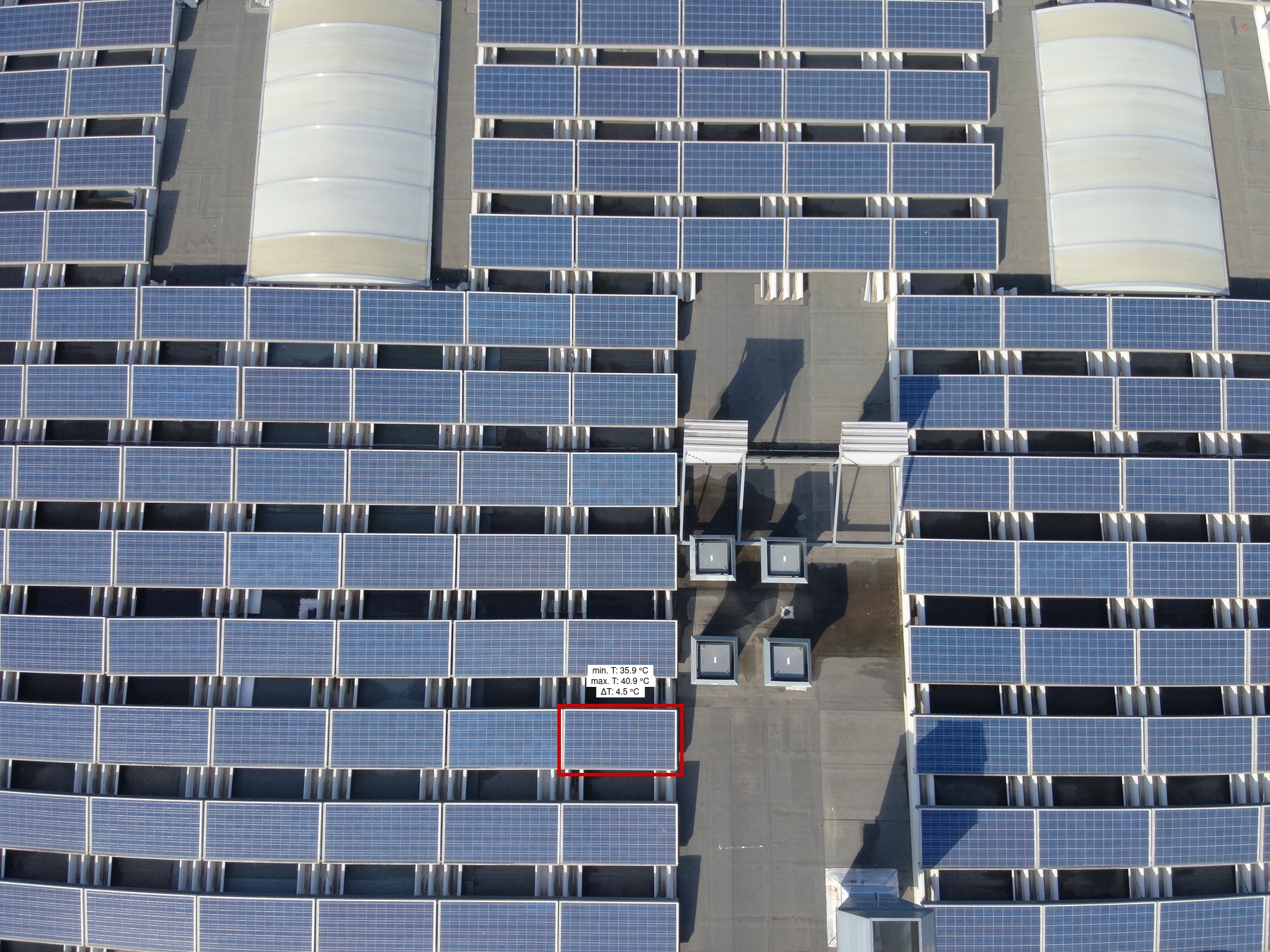
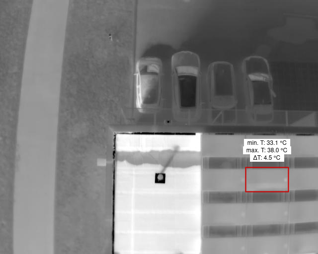
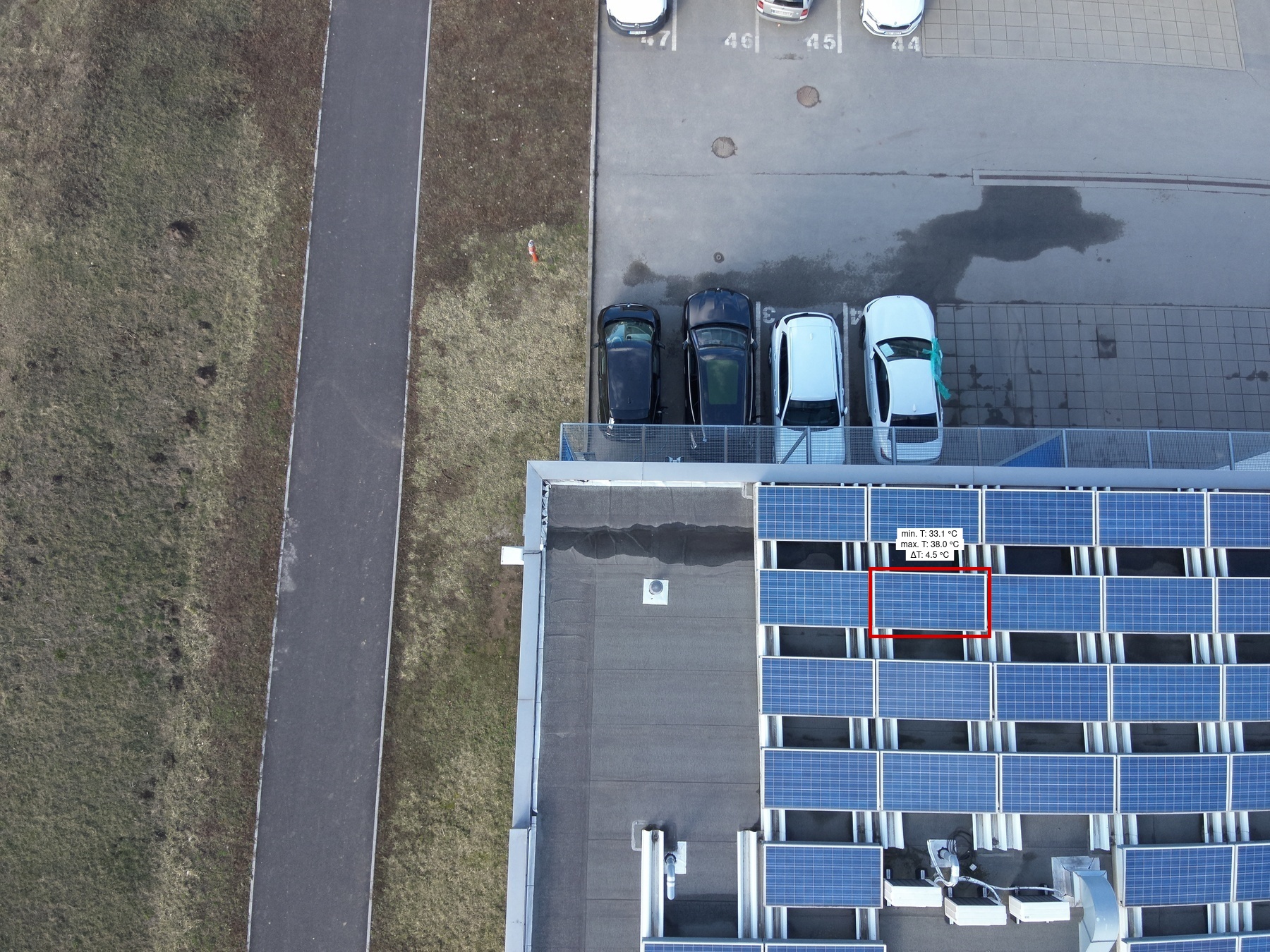
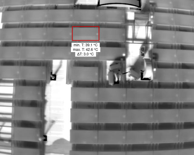
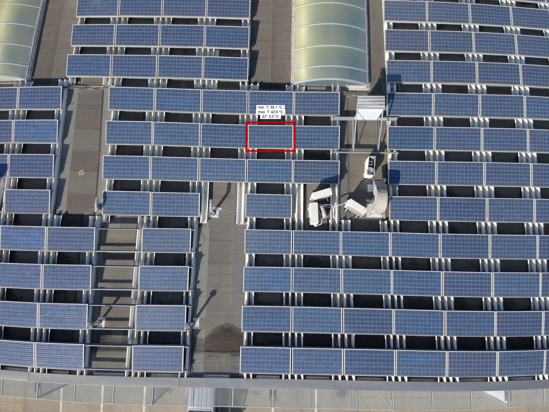
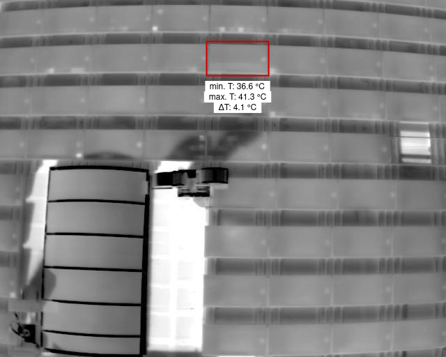
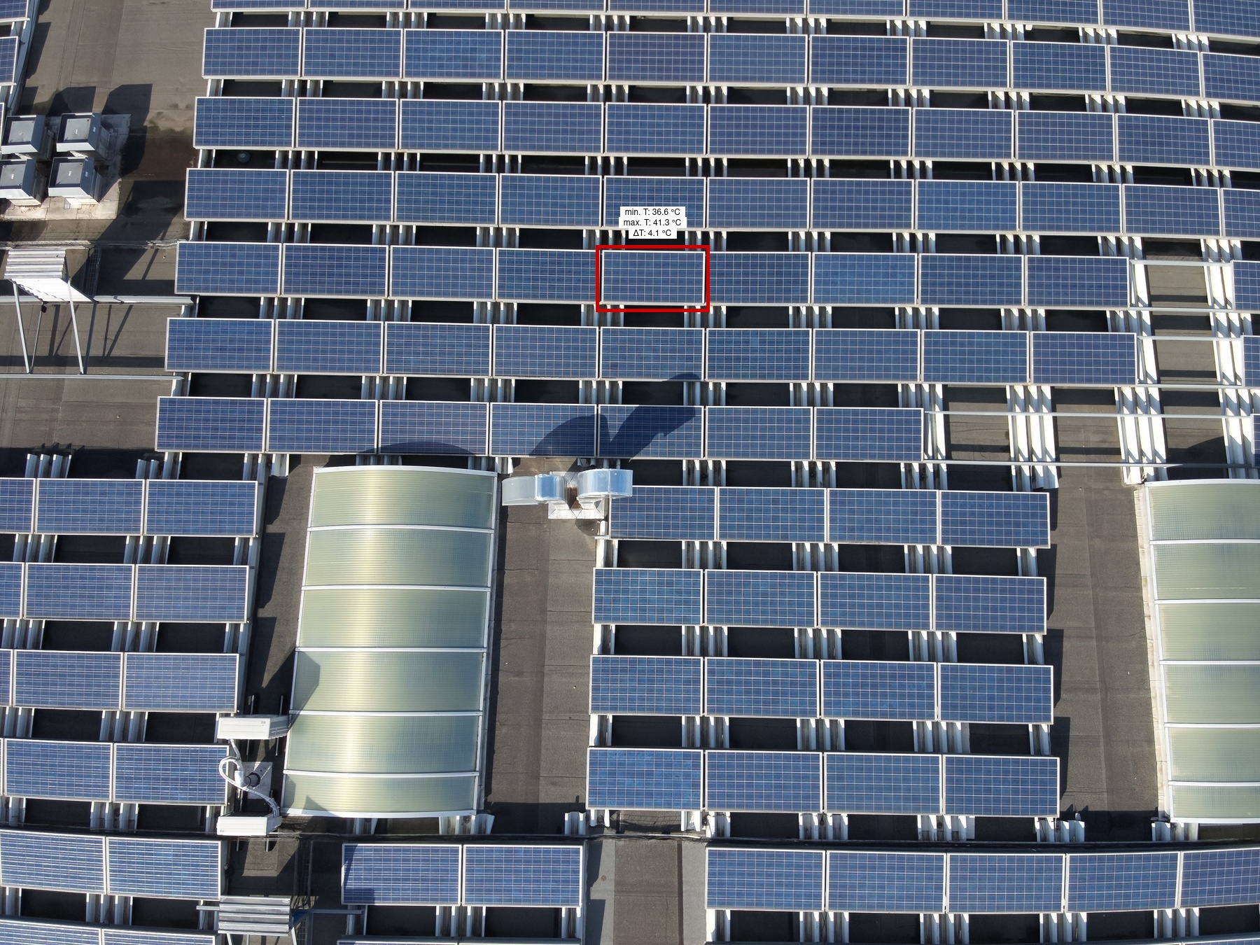
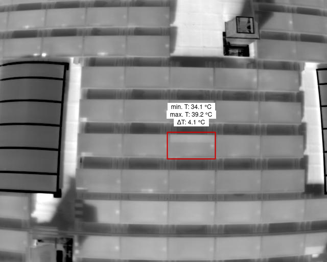
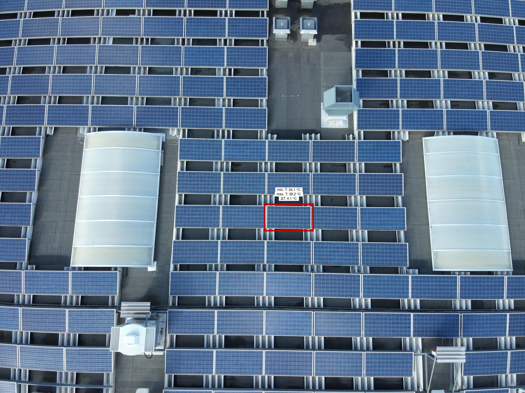
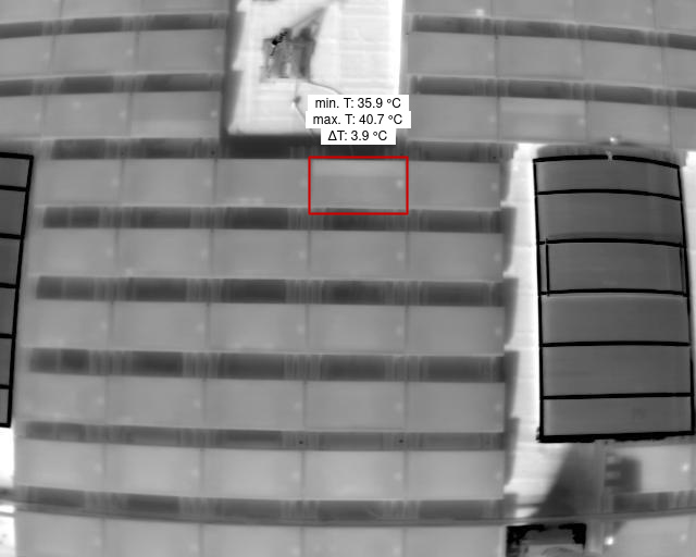
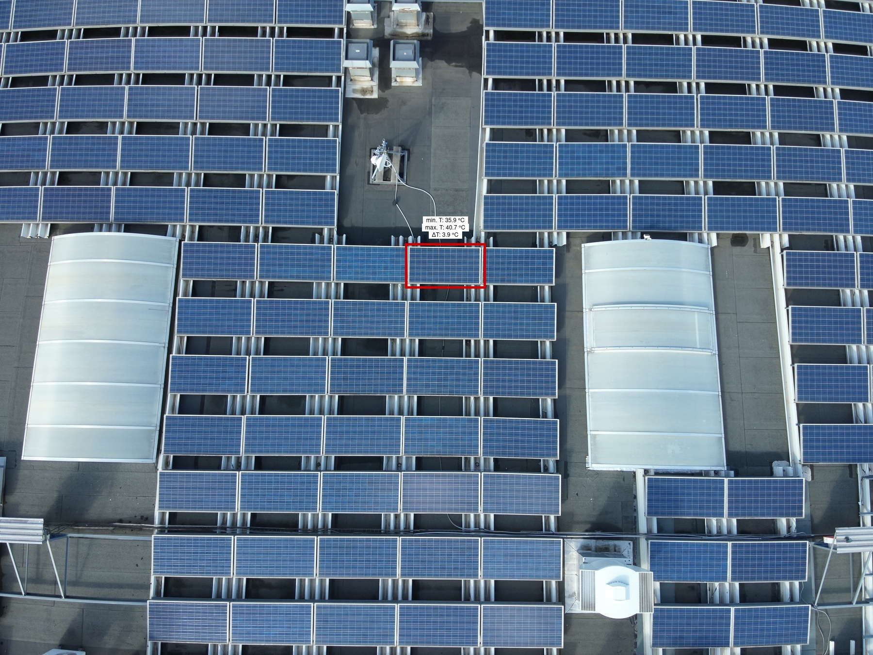
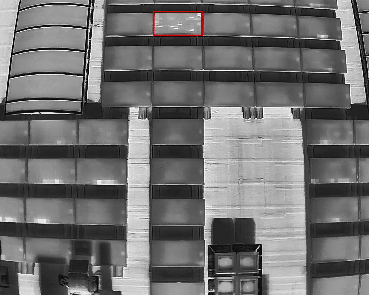
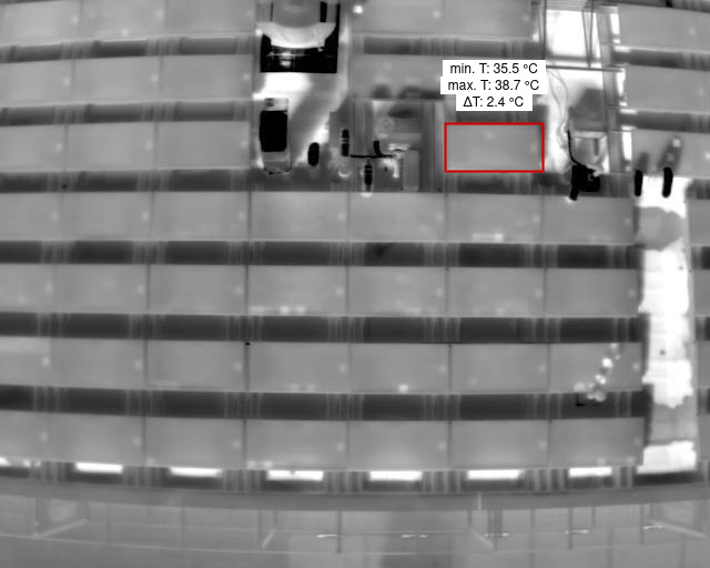
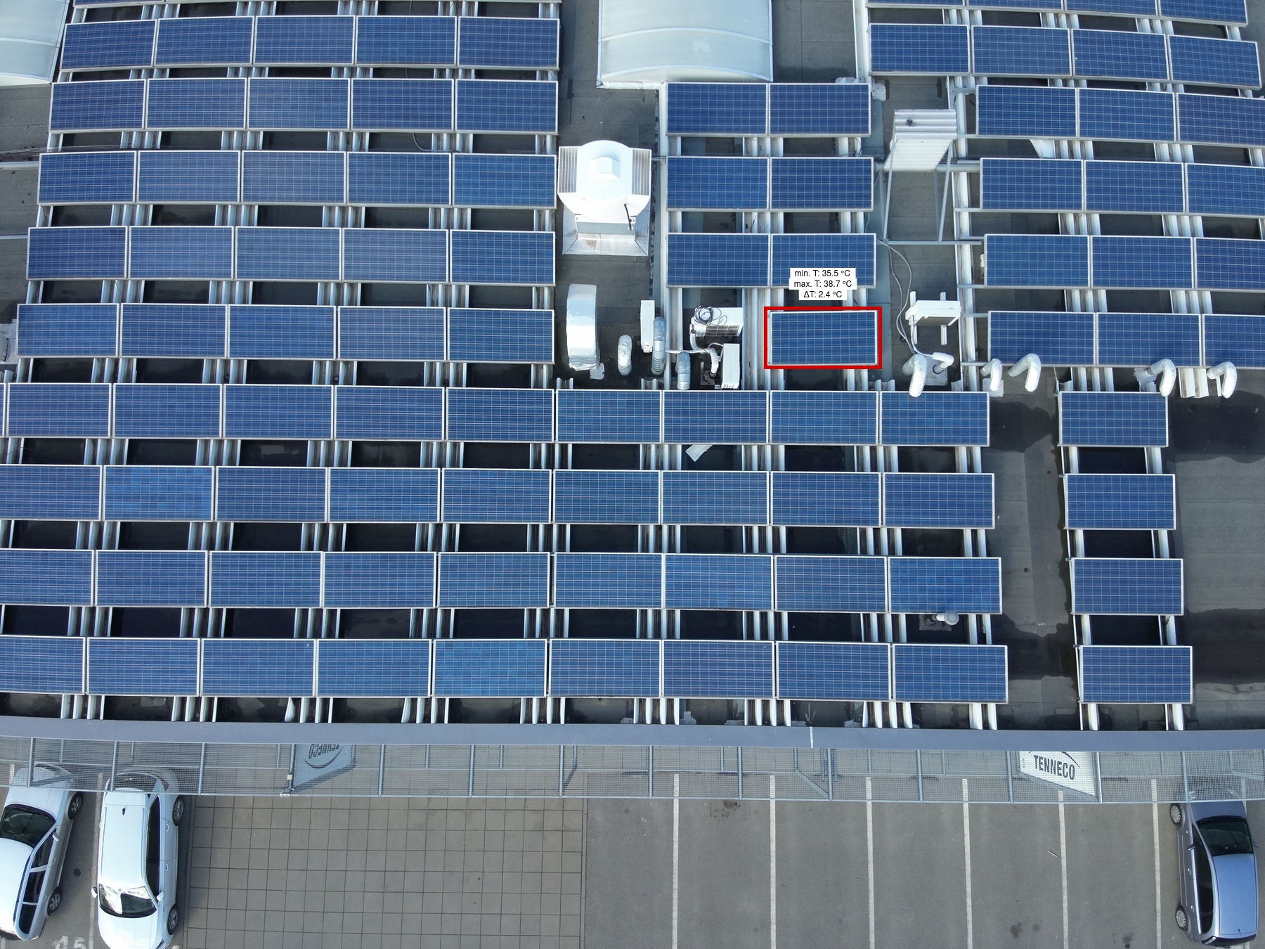
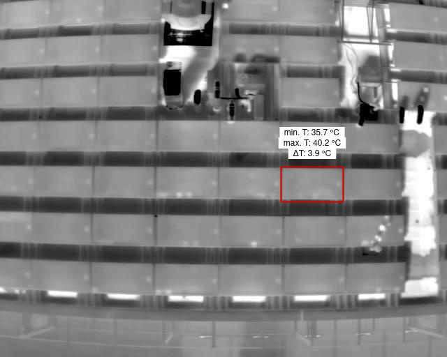
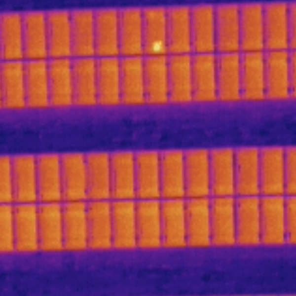
Diode |
1 | 94 | 1 | 1 | 22 | 1 | Medium | 3.9 | |
|
|
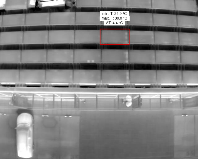
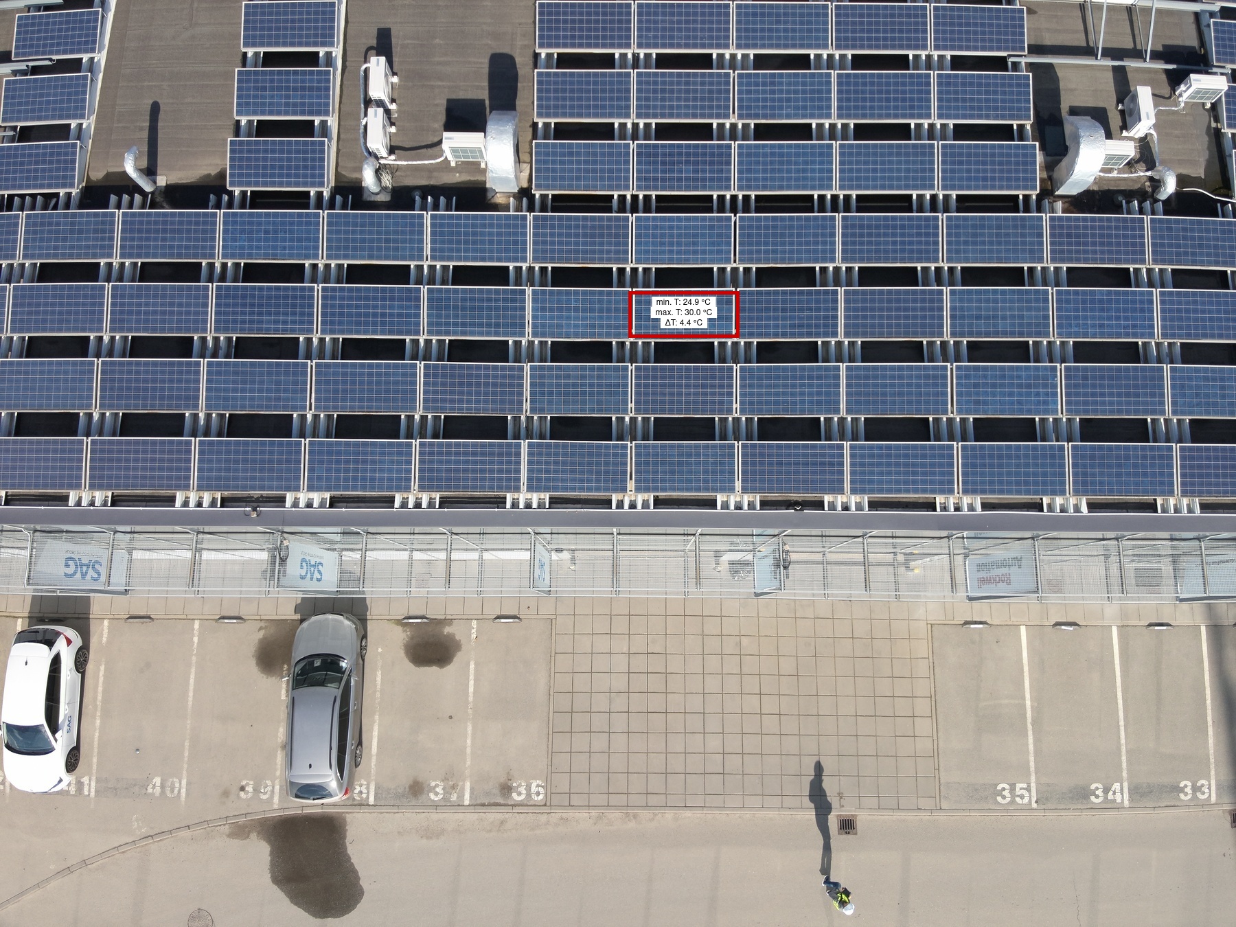
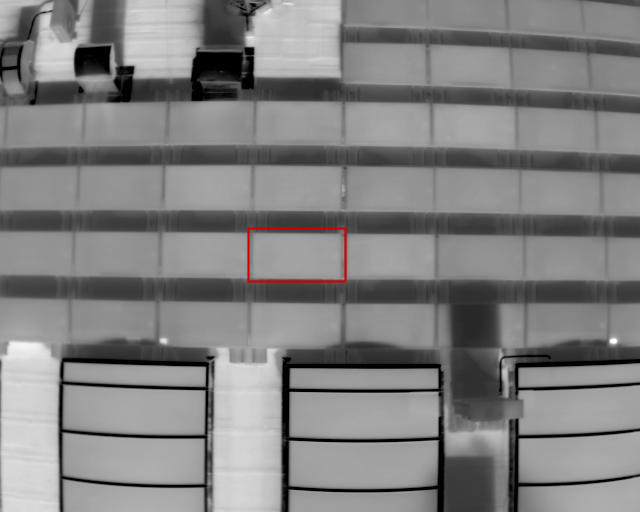
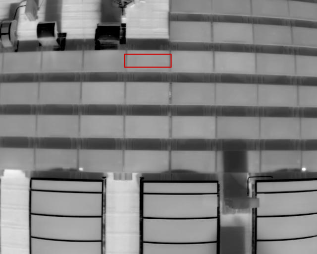
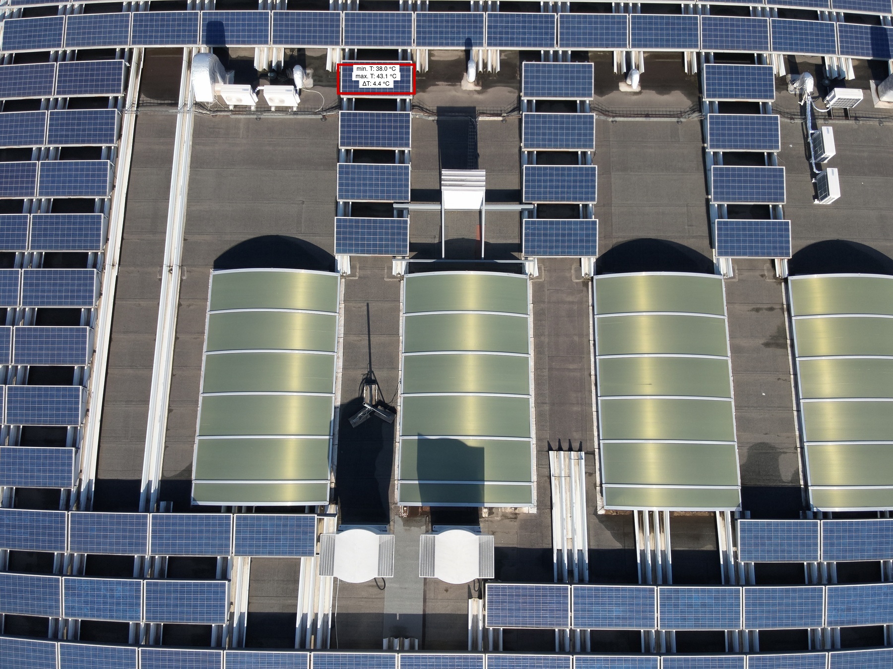
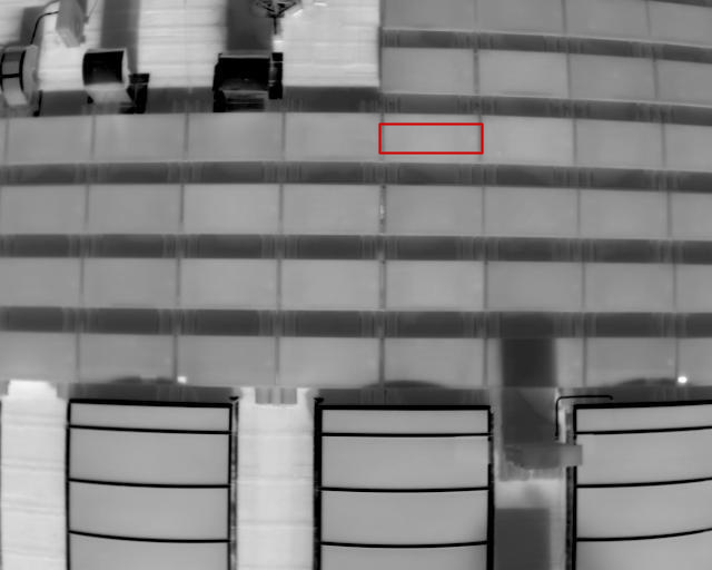
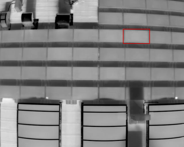
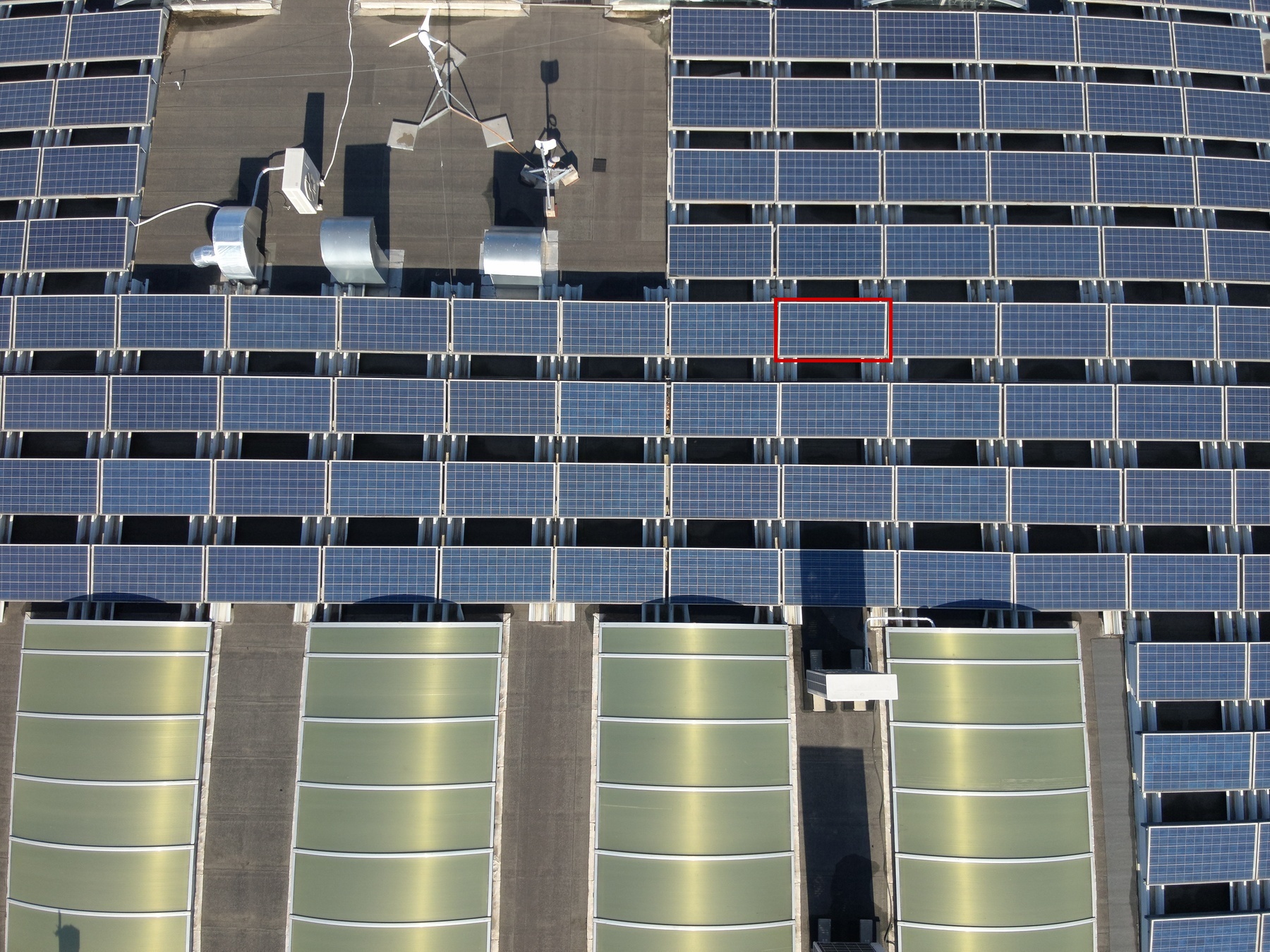
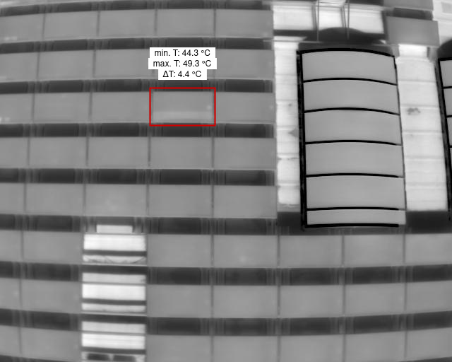
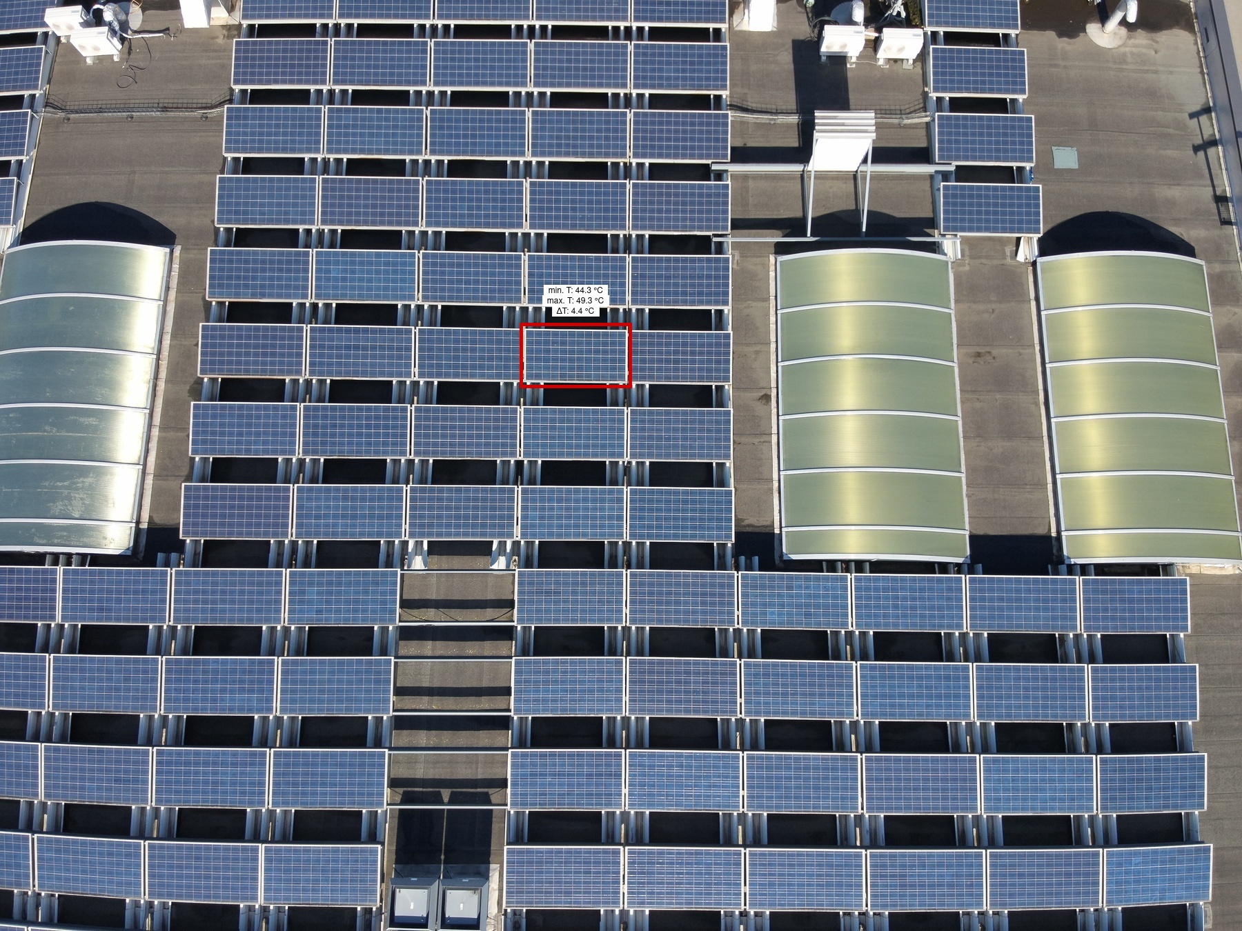
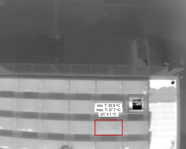
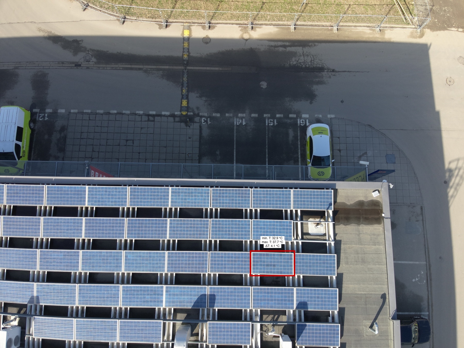
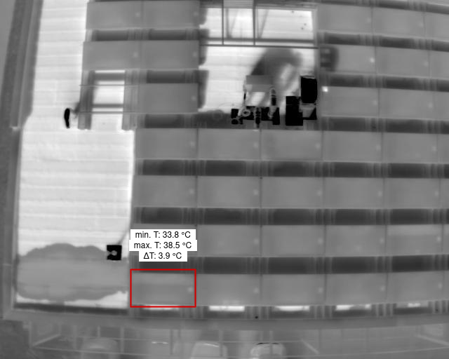
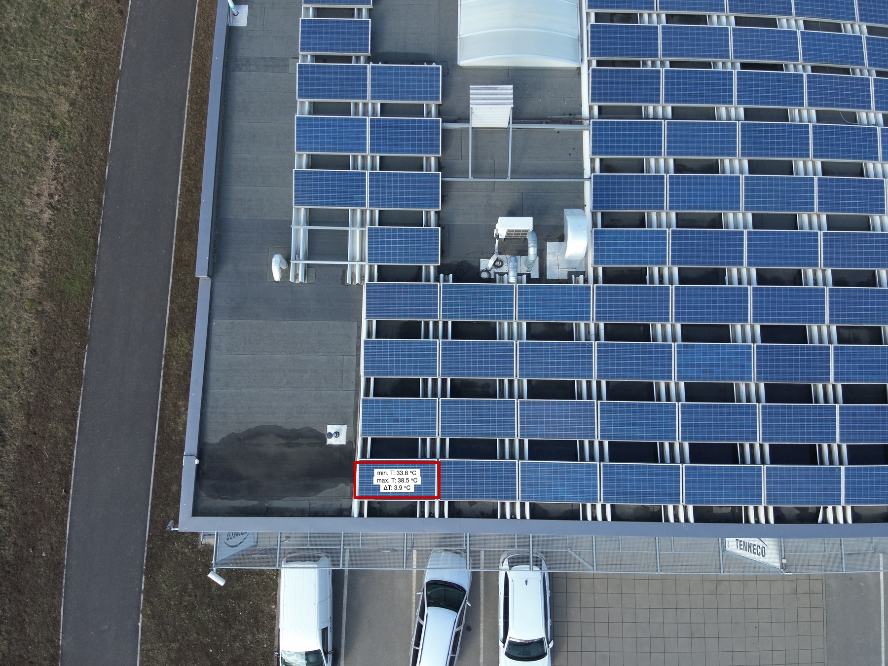
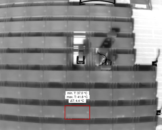
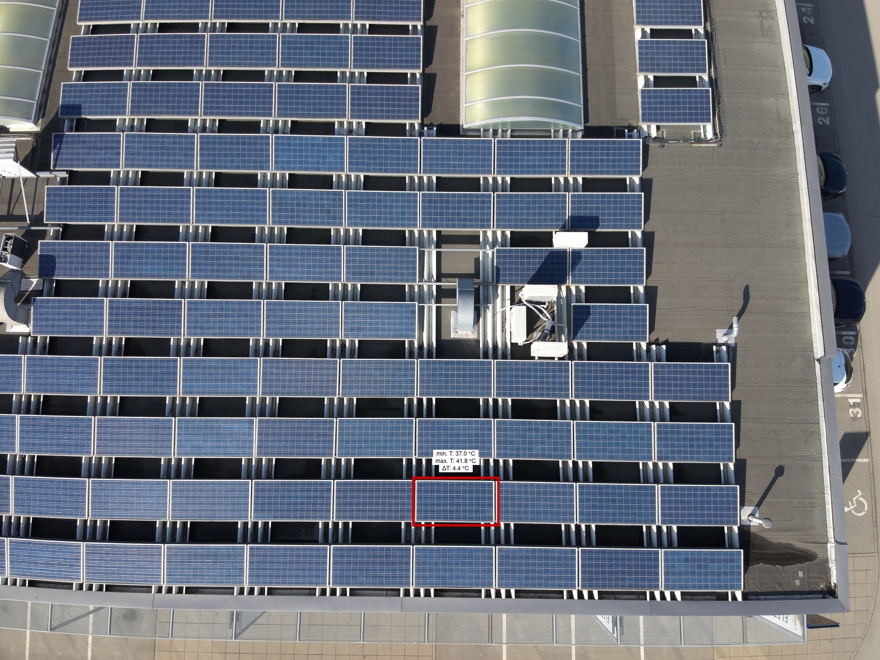
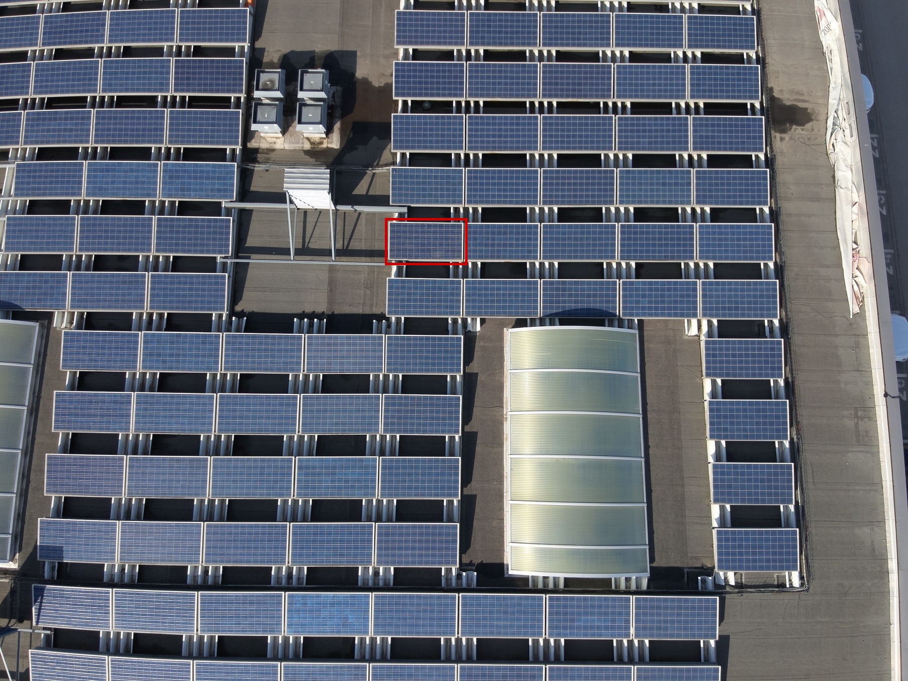
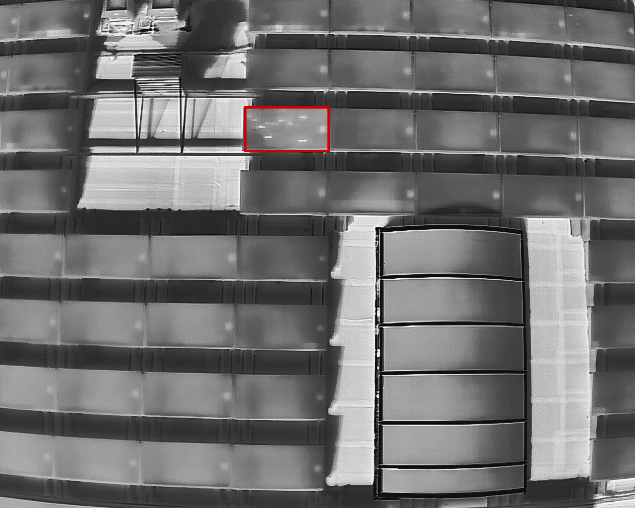
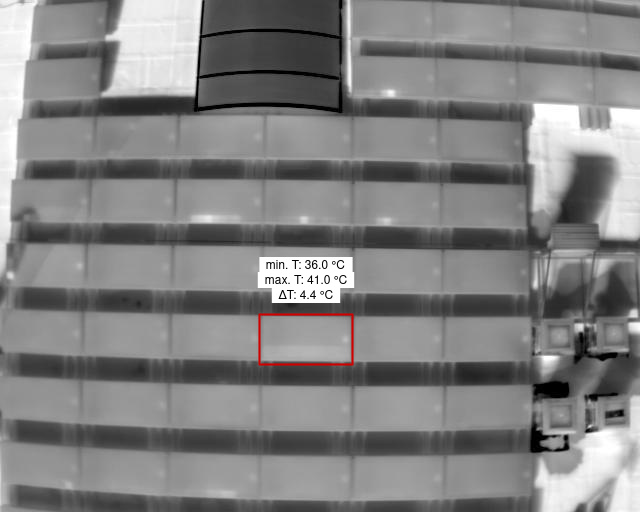
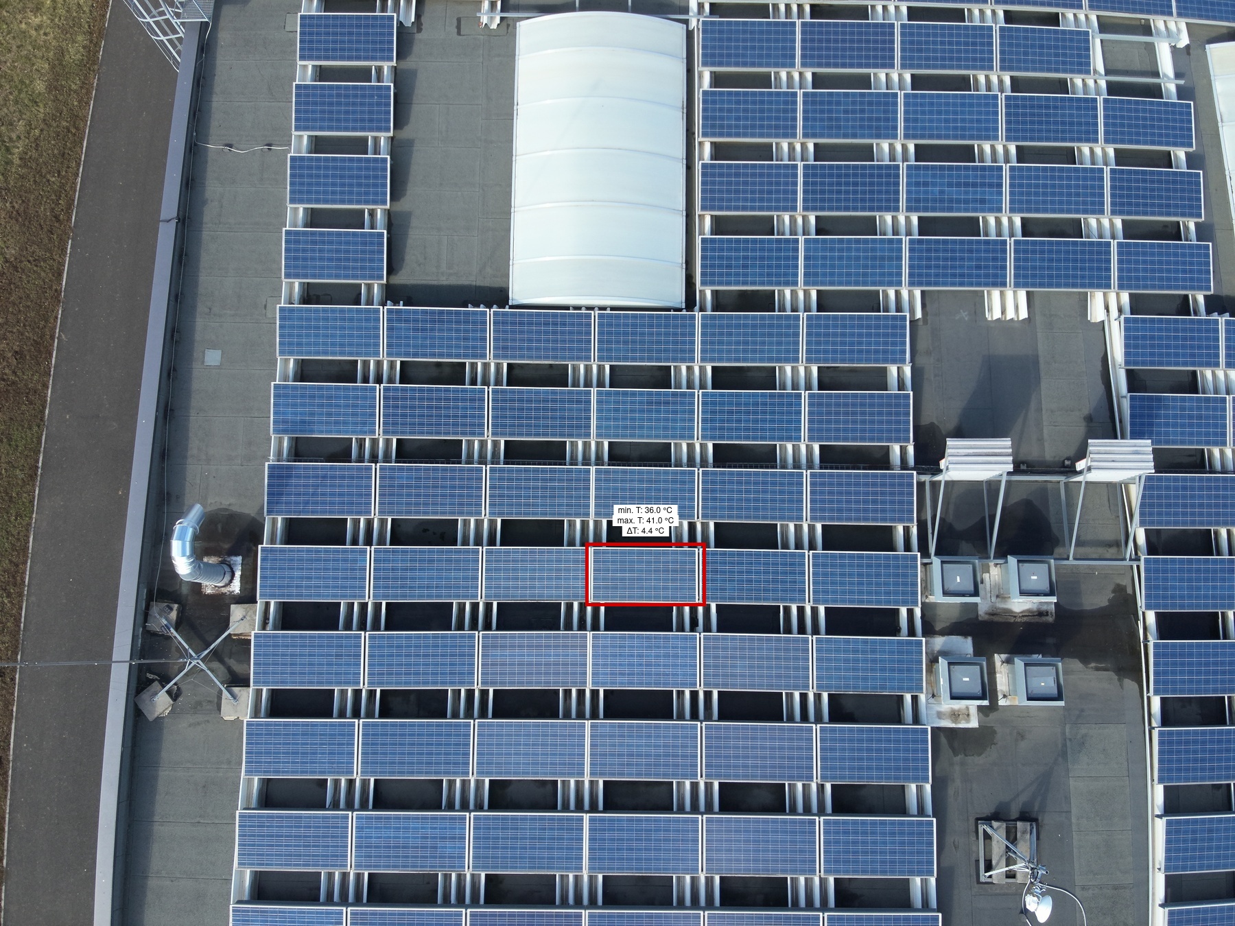
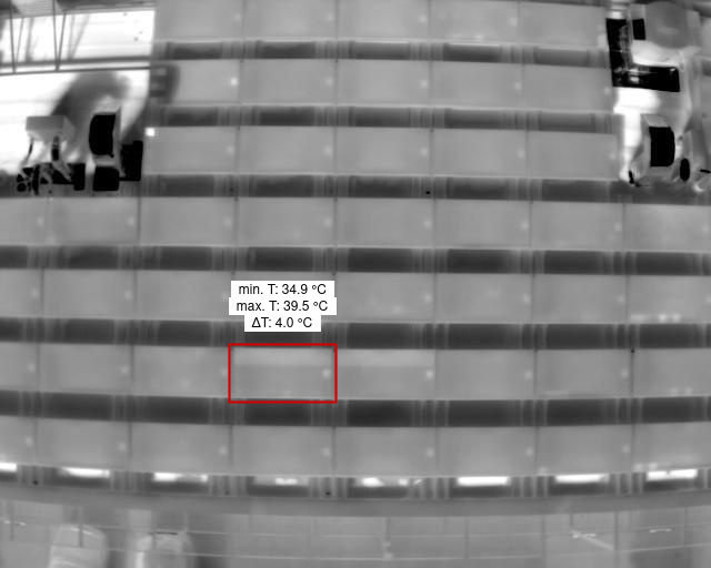
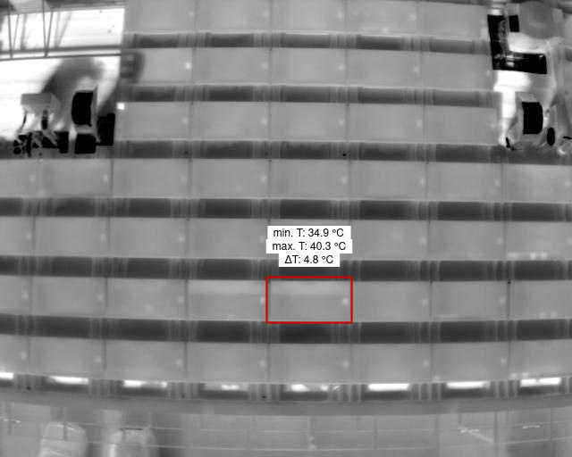
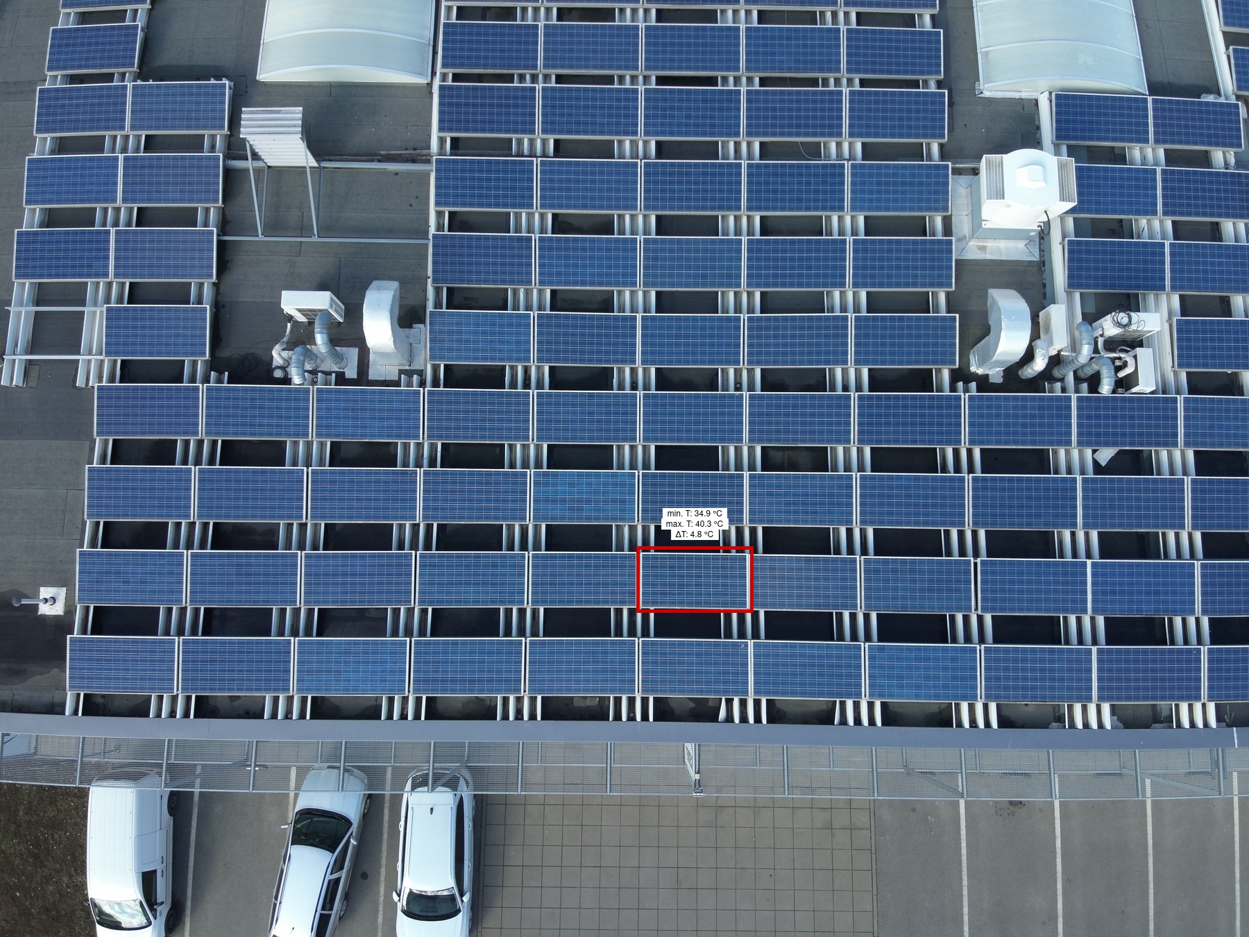
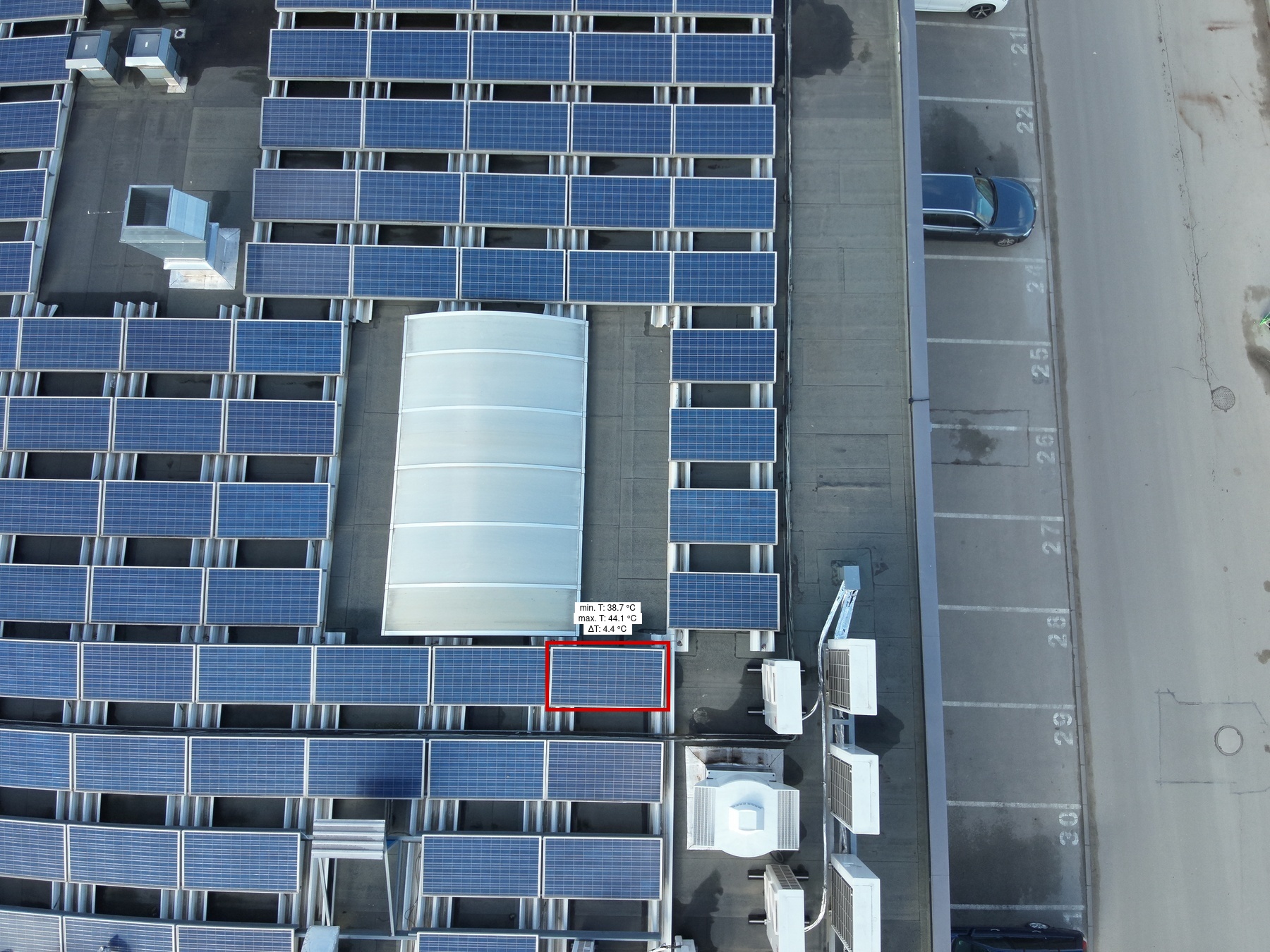
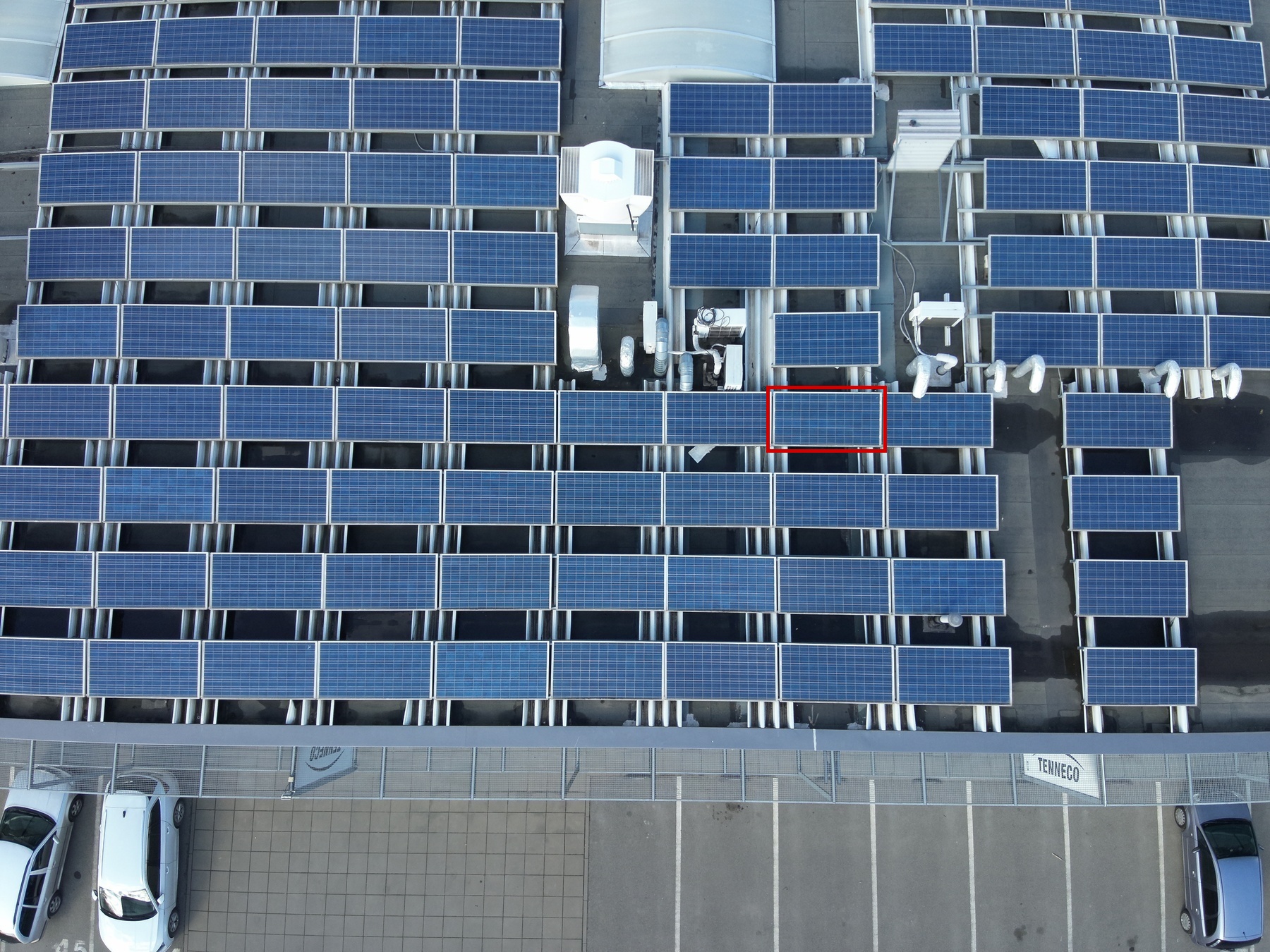
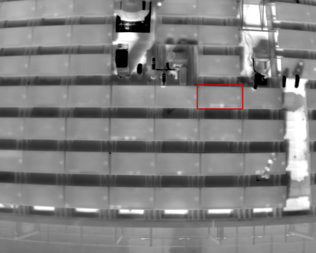
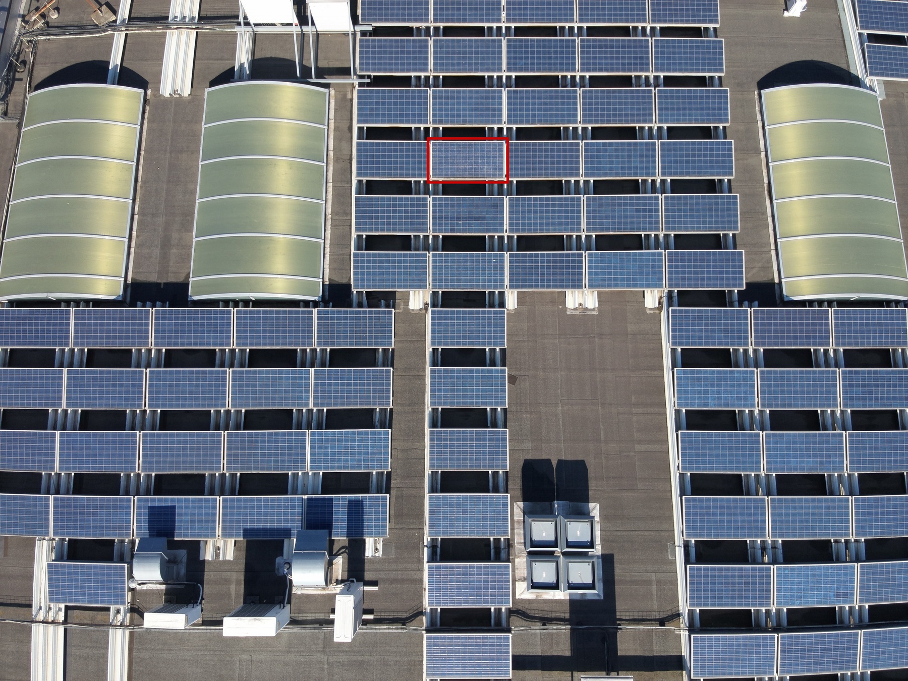
Cell Multi Low |
1 | 94 | 1 | 1 | 21 | 1 | Low | 4.4 | |
|
|
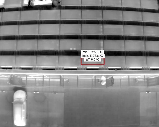
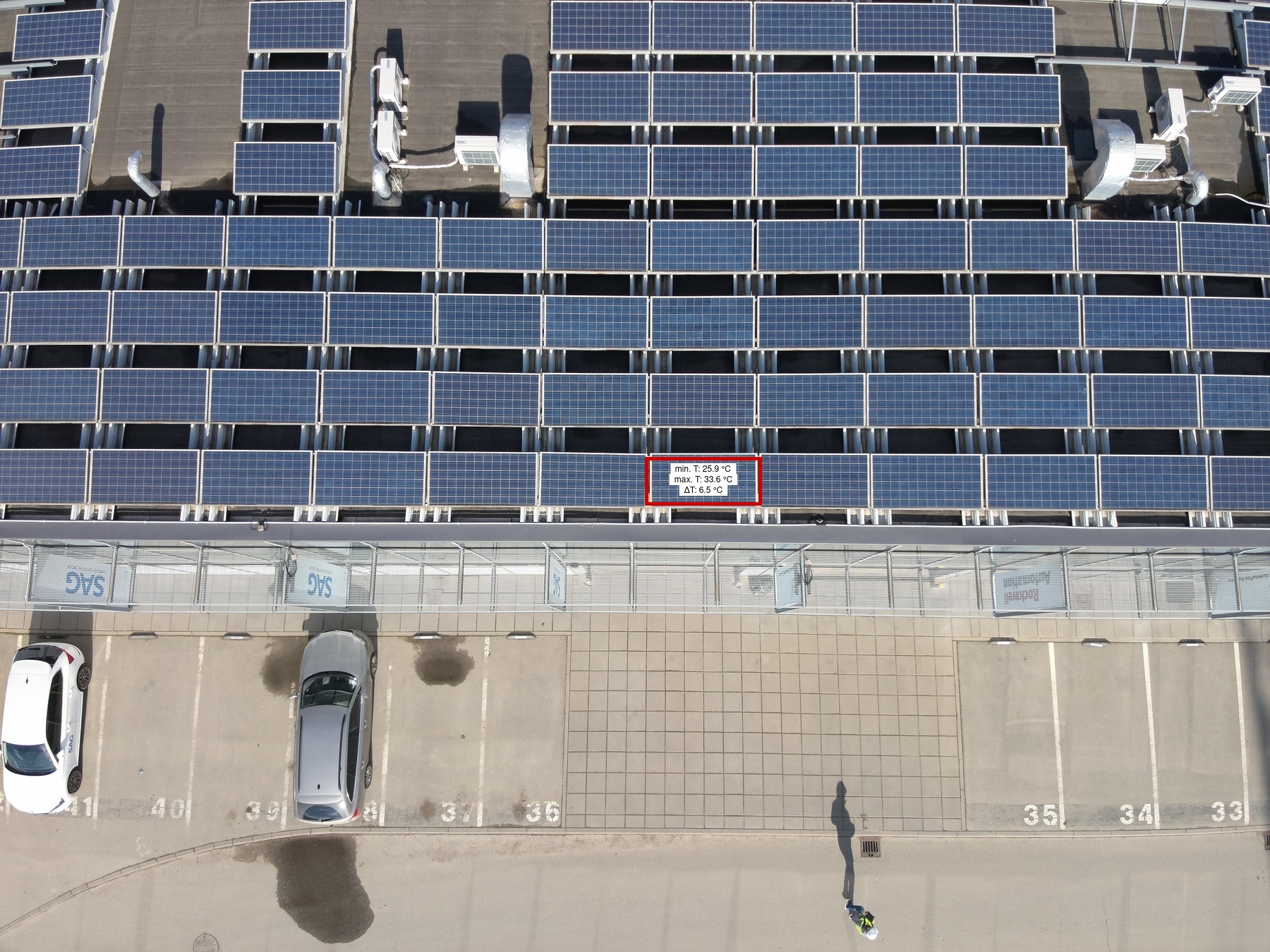
Cell Multi Low |
1 | 96 | 1 | 1 | 21 | 1 | Low | 6.5 | |
|
|
Cell Multi Low |
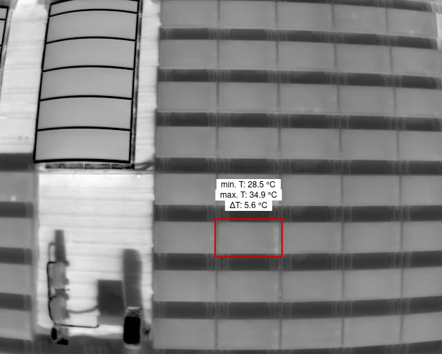
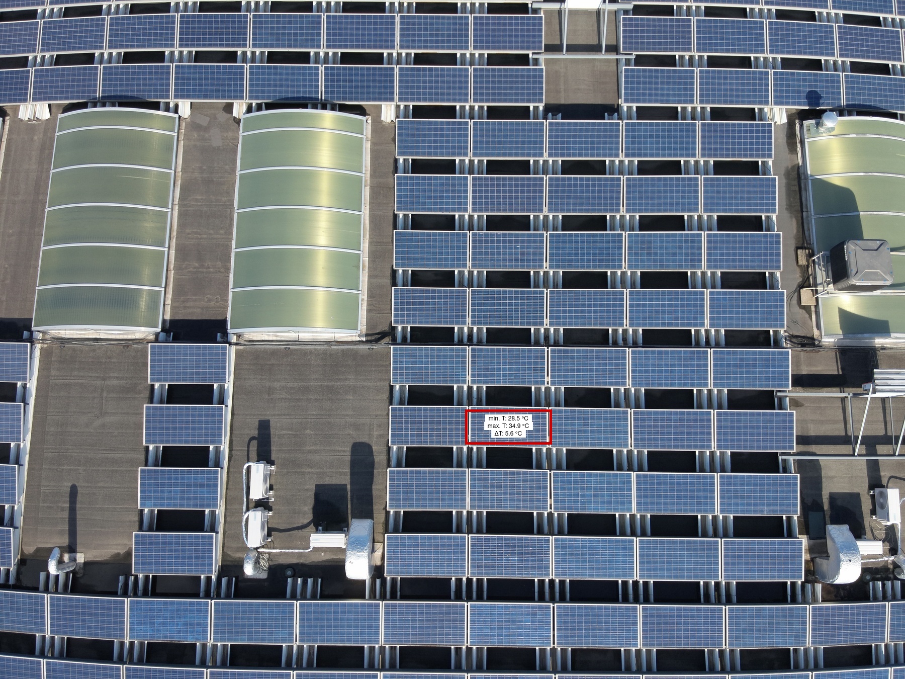
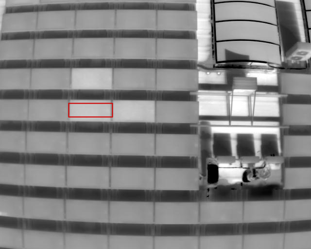
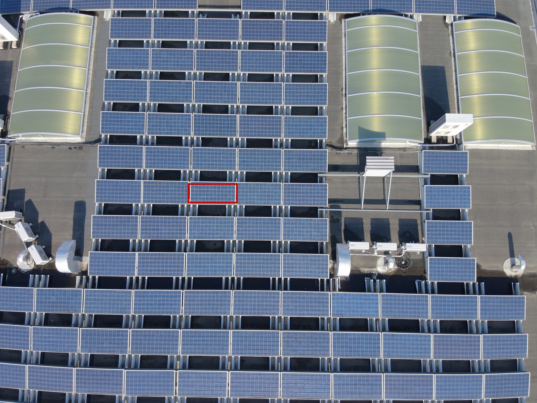
1 | 90F | 1 | 1 | 2 | 1 | Low | 5.6 | |
|
|
Cell Multi Medium |
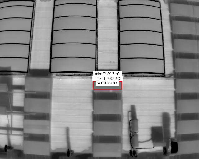
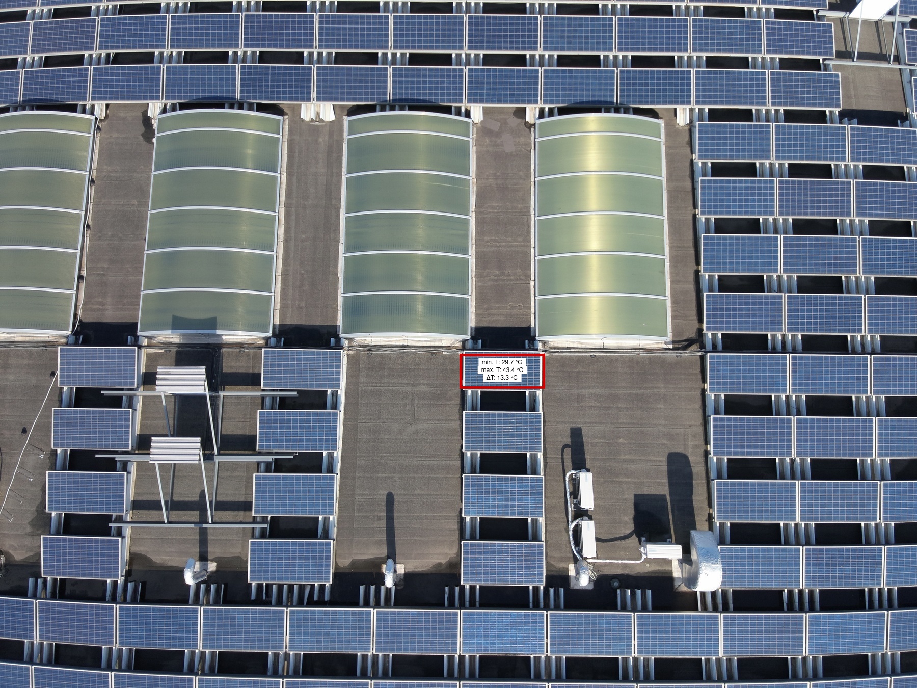
1 | 89E | 1 | 1 | 1 | 1 | Low | 13.3 | |
|
|
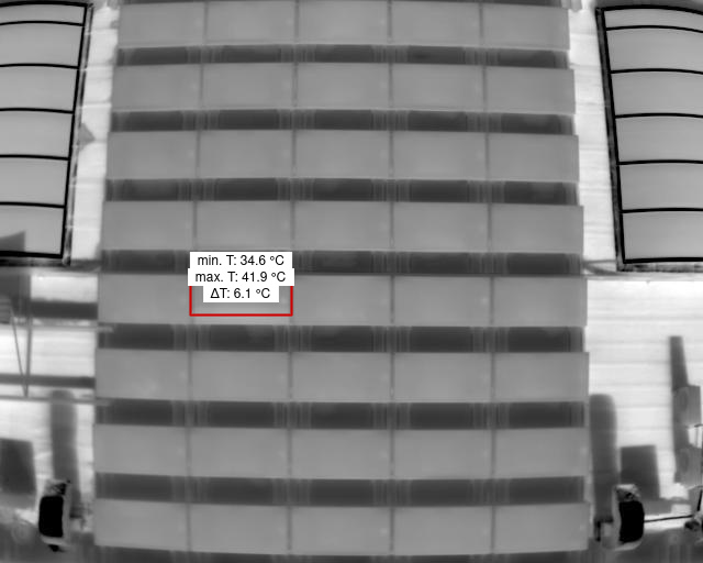
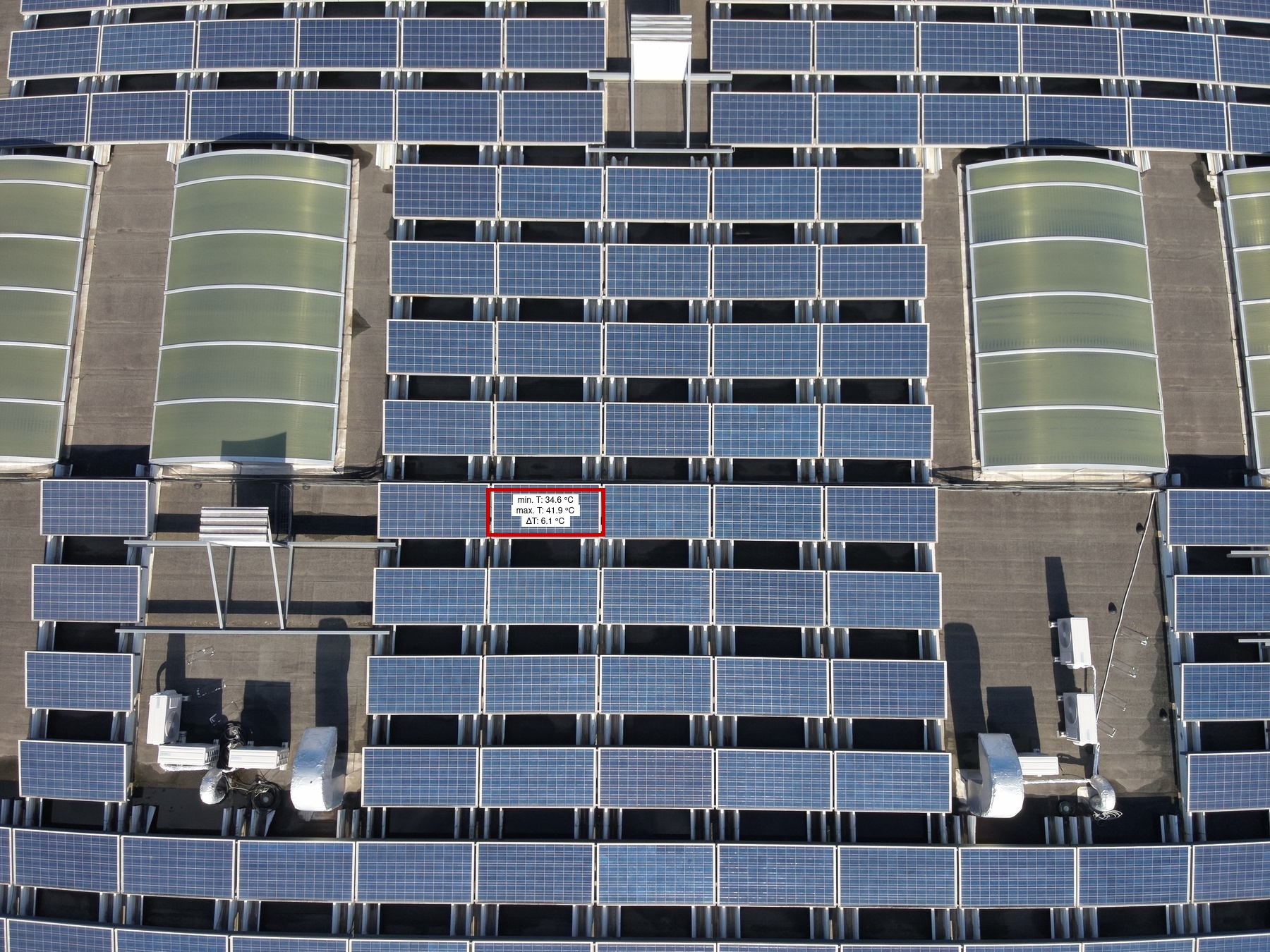
Diode |
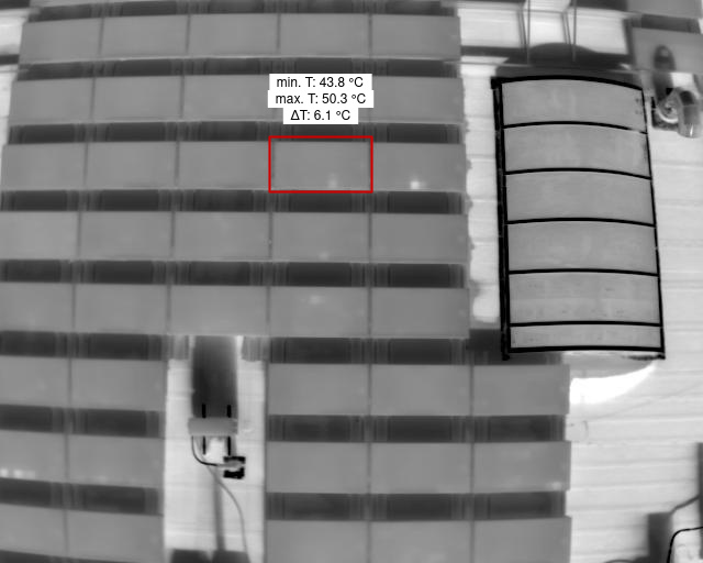
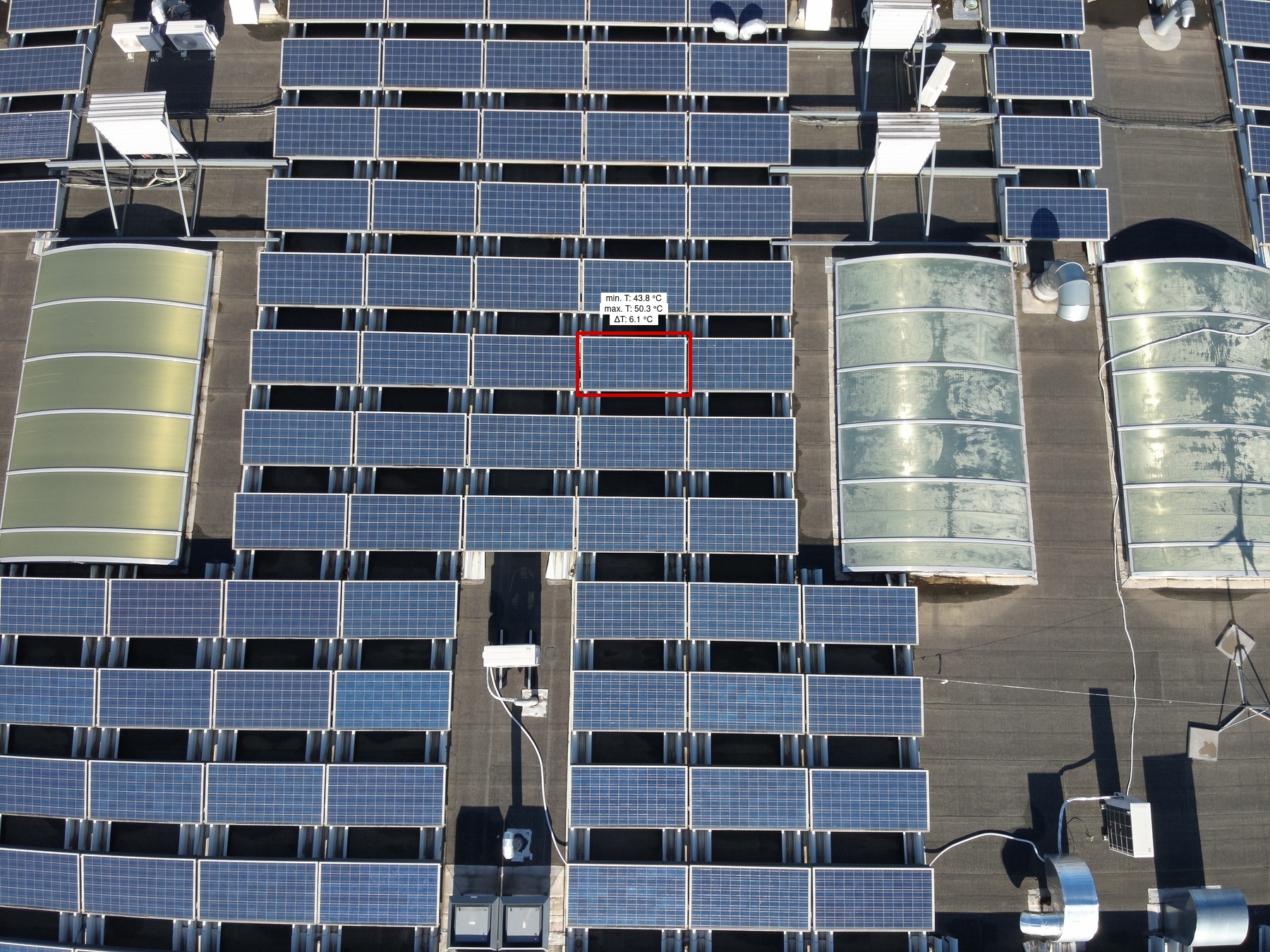
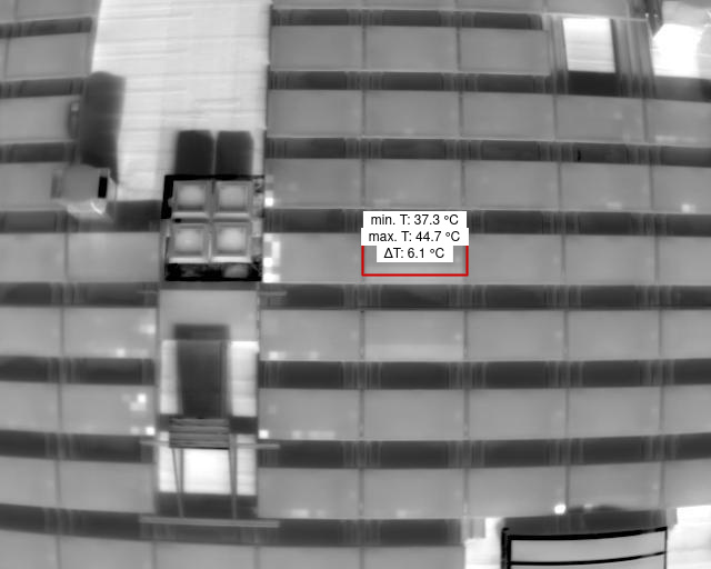
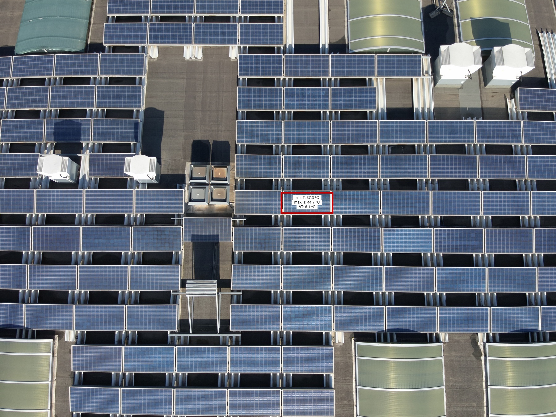
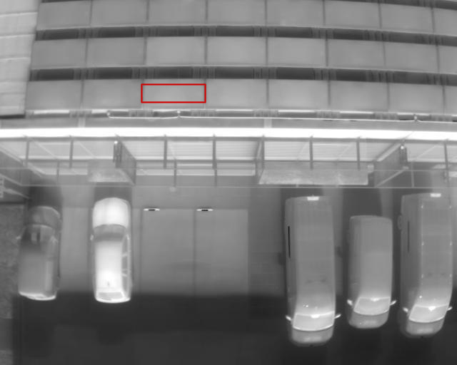
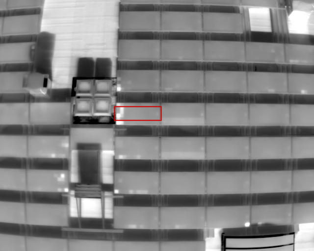
1 | 89B | 1 | 1 | 2 | 1 | Medium | 6.1 | |
|

|
Module |
1 | 59B | 1 | 1 | 5 | 1 | High | ||
|
|
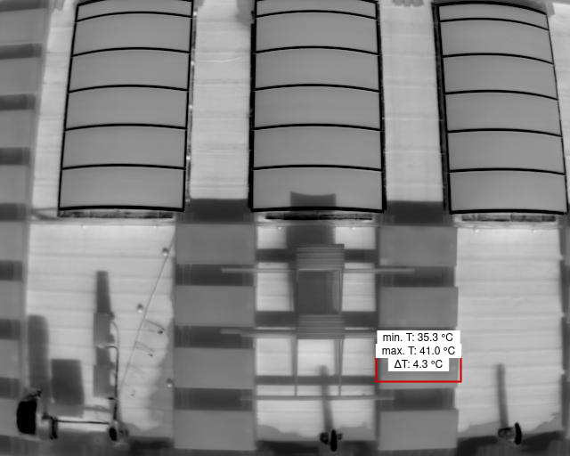
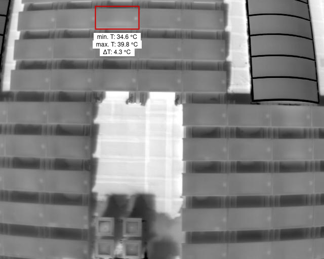
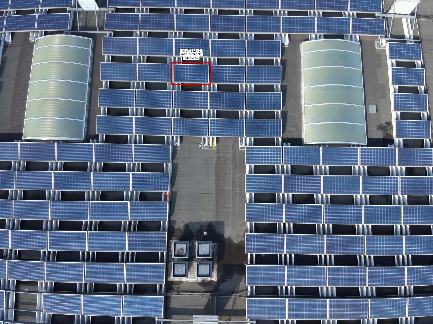
Diode Multi |
1 | 91D | 1 | 1 | 1 | 1 | Medium | 4.3 | |
|
|
Module |
1 | 58B | 1 | 1 | 5 | 1 | High | ||
|
|
Module |
1 | 58B | 1 | 1 | 4 | 1 | High | ||
|
|
Module |
1 | 57B | 1 | 1 | 4 | 1 | High | ||
|
|
Diode |
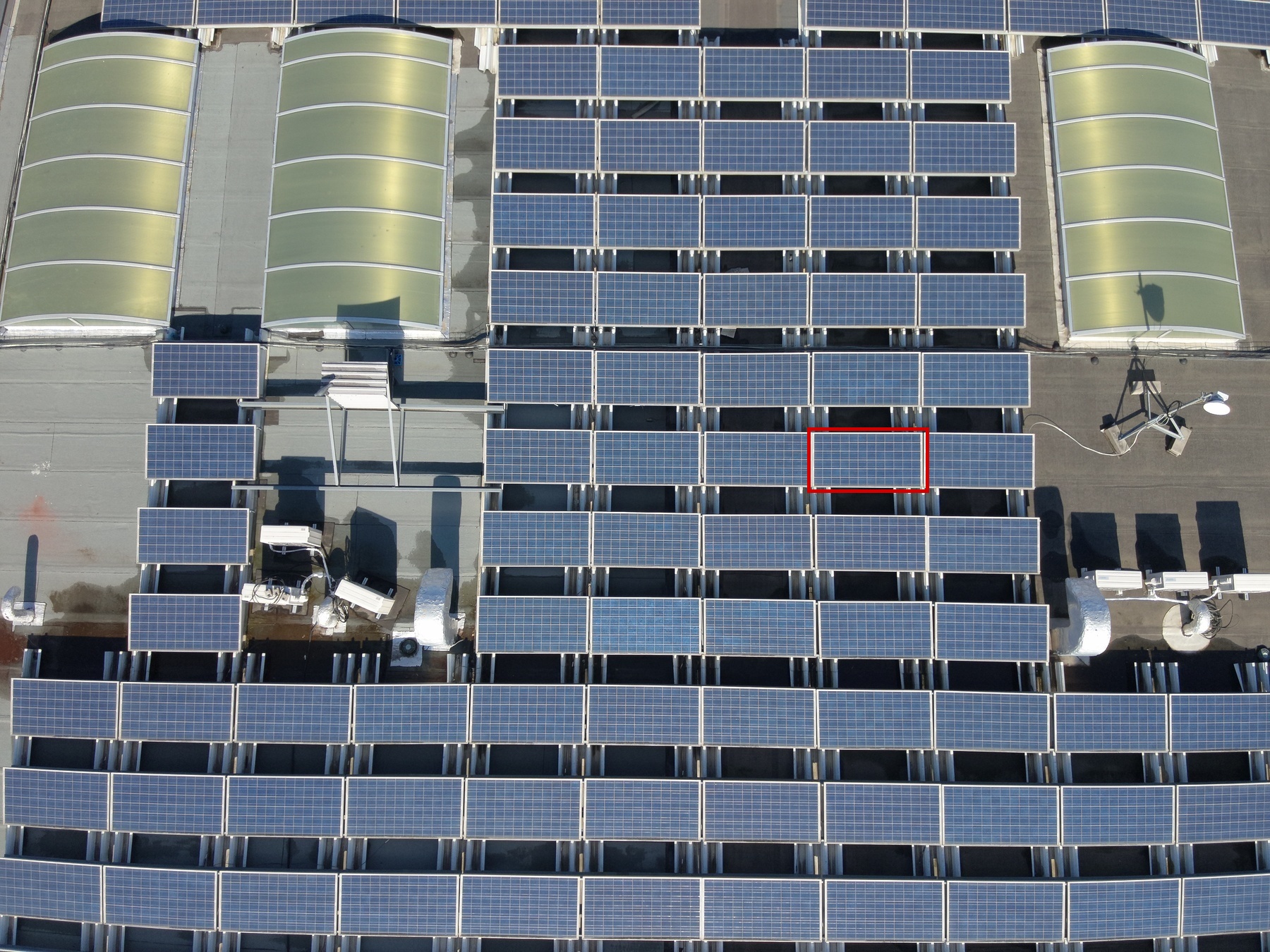
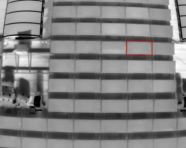
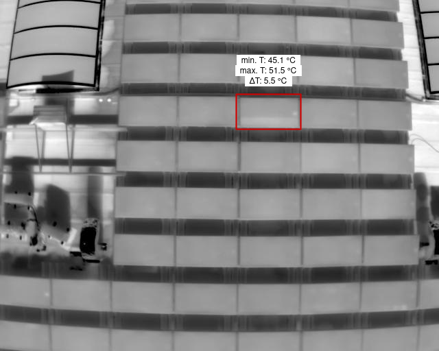
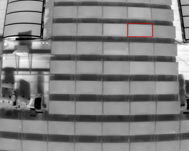
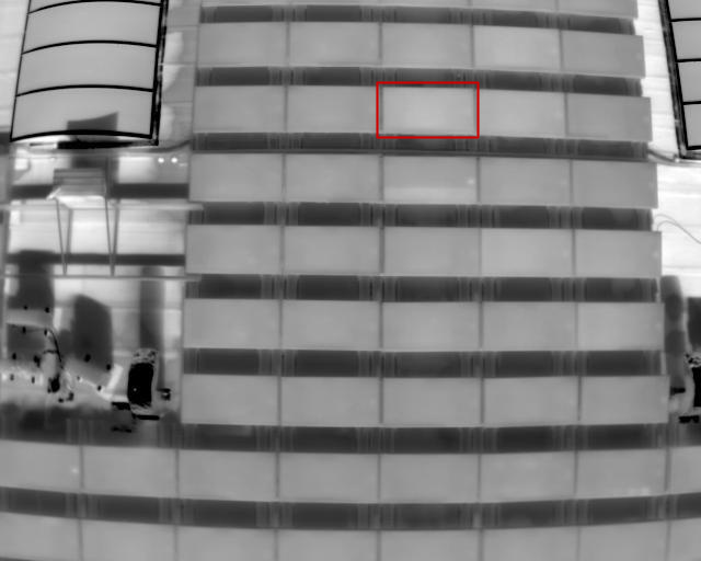
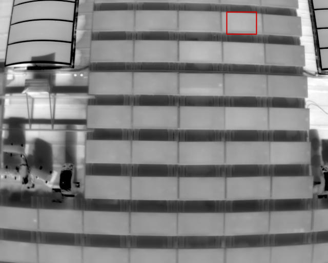
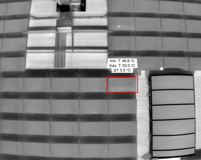
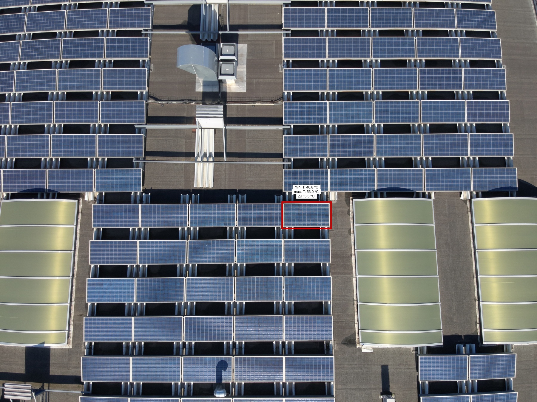
1 | 57B | 1 | 1 | 3 | 1 | Medium | 5.5 | |
|

|
Module |
1 | 56A | 1 | 1 | 4 | 1 | High | ||
|

|
Module |
1 | 56A | 1 | 1 | 3 | 1 | High | ||
|
|
Module |
1 | 55A | 1 | 1 | 4 | 1 | High | ||
|
|
Diode |
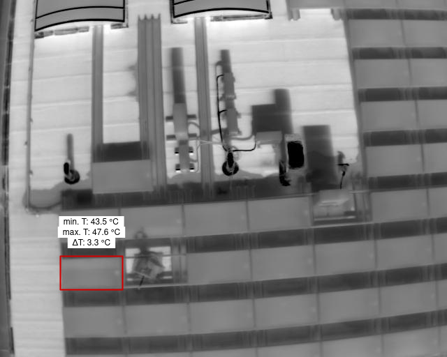
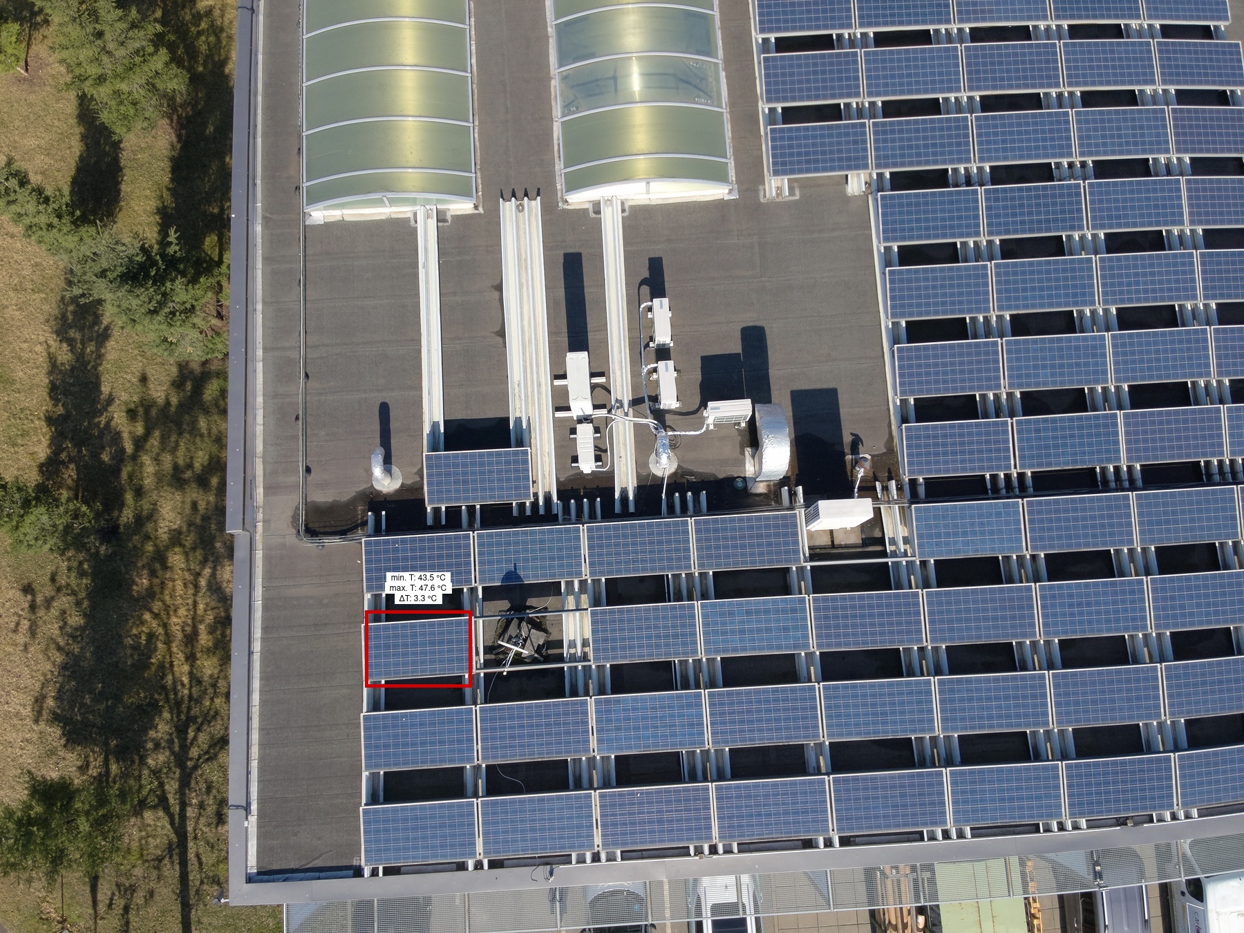
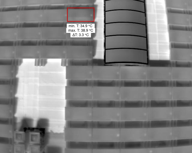
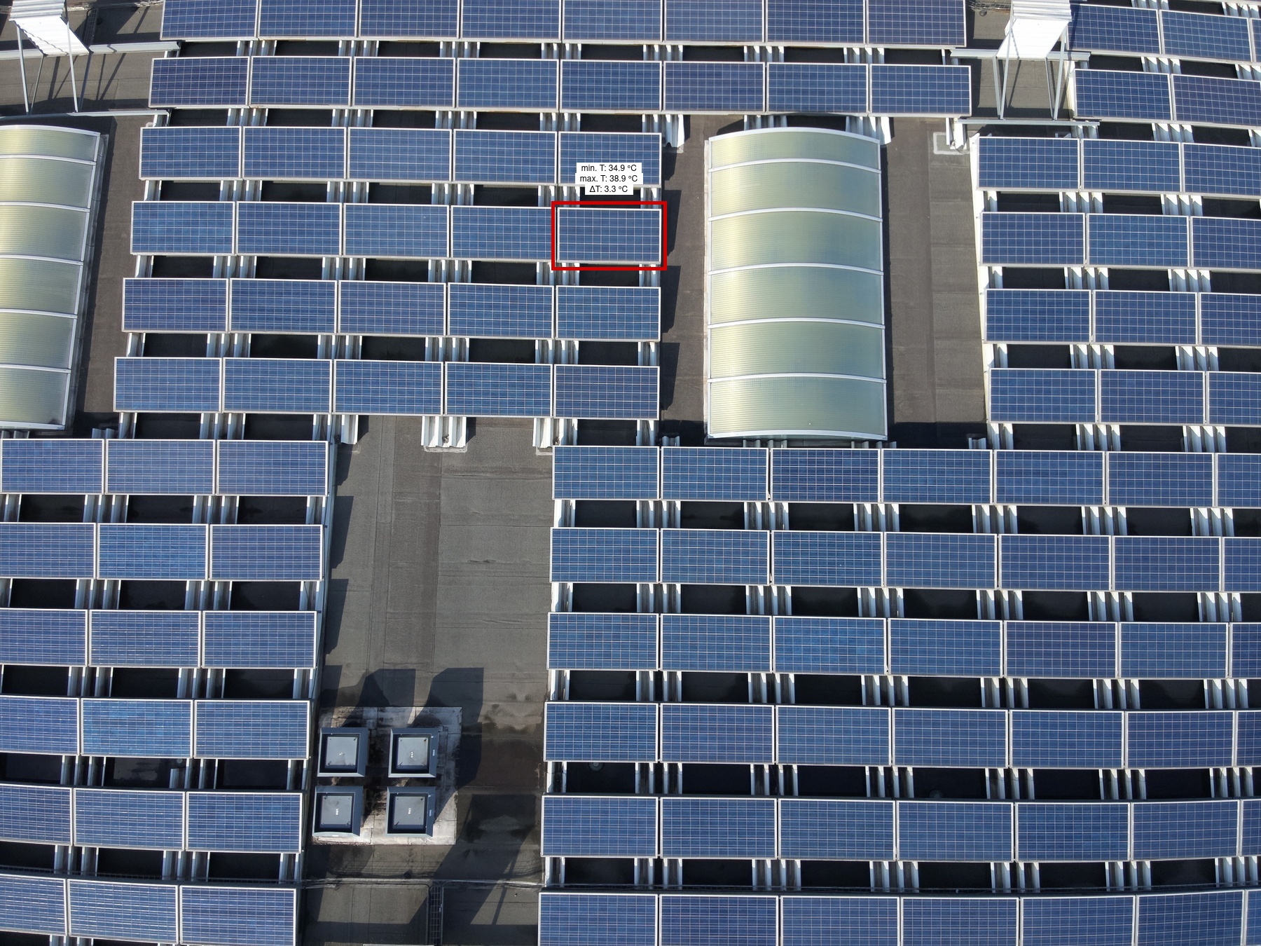
1 | 51B | 1 | 1 | 1 | 1 | Medium | 3.3 | |
|

|
Module |
1 | 51B | 1 | 1 | 7 | 1 | High | ||
|
|
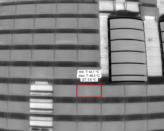
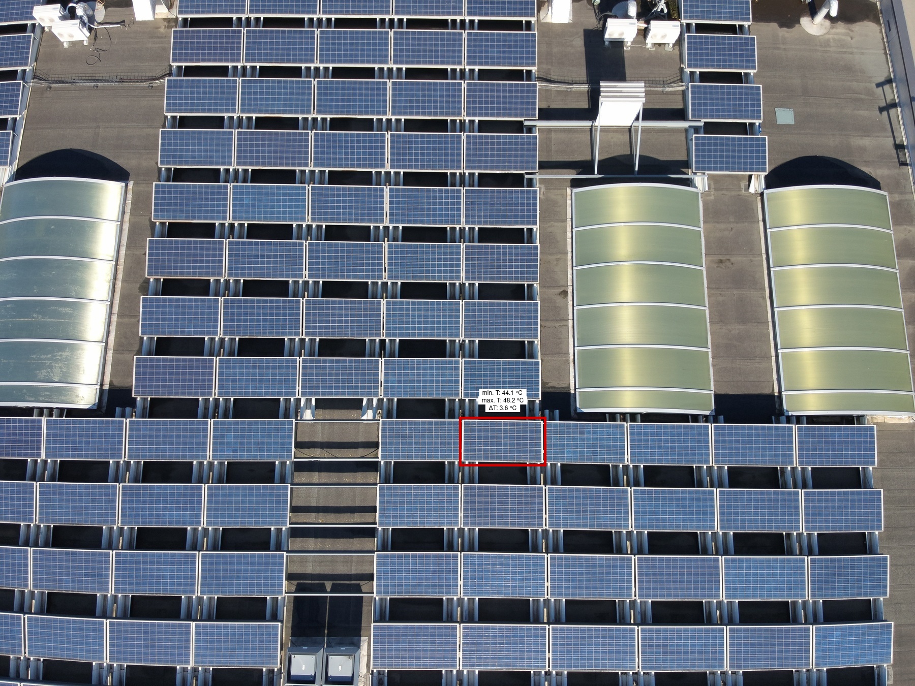
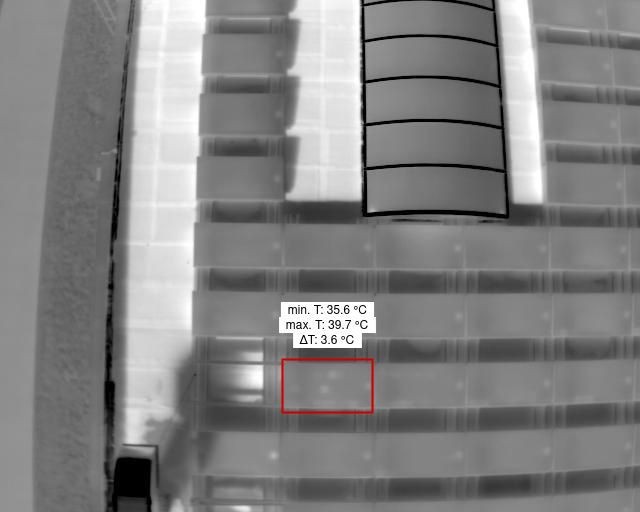
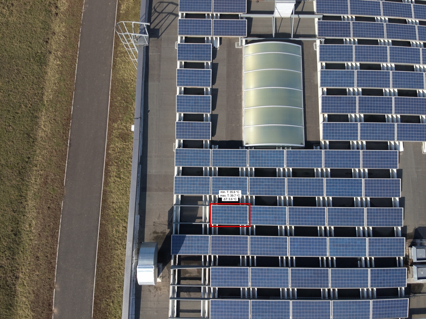
Cell Low |
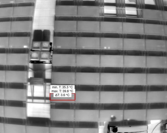
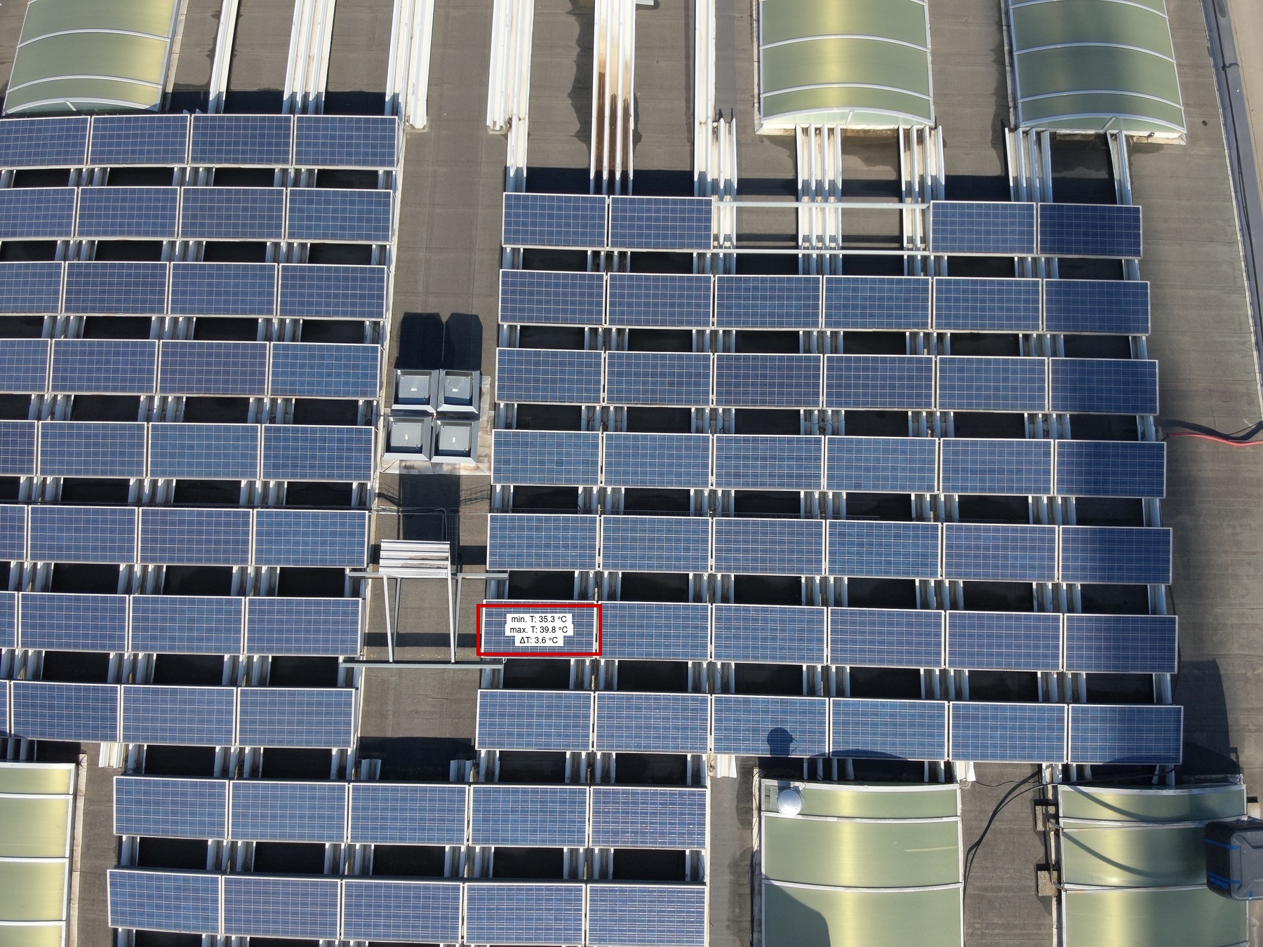
1 | 45D | 1 | 1 | 2 | 1 | Low | 3.6 | |
|
|
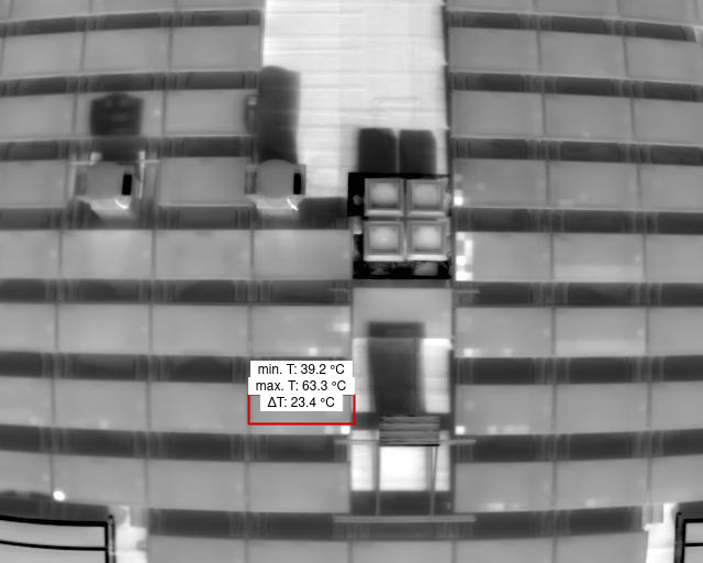
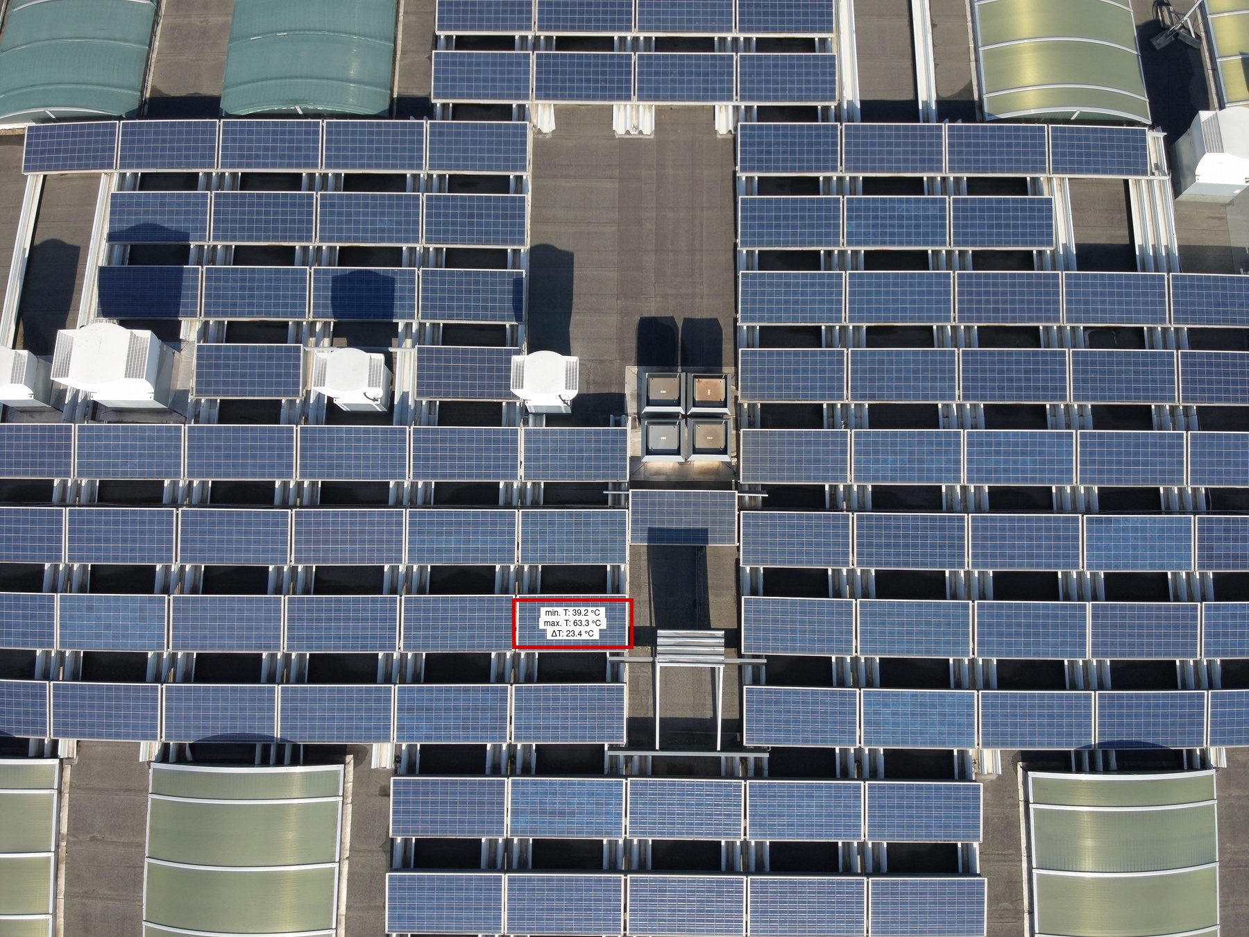
Cell Multi High |
1 | 83A | 1 | 1 | 6 | 1 | Low | 23.4 | |
|
|
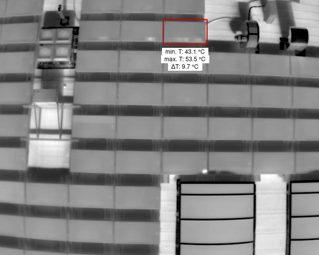
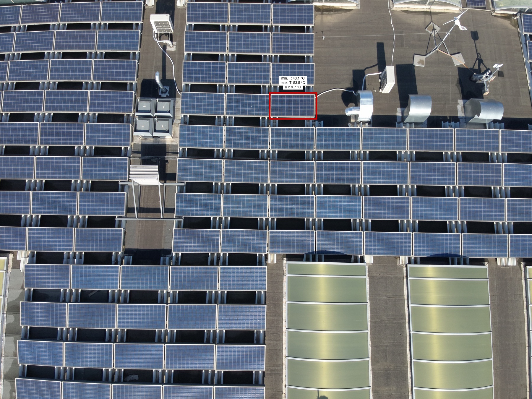
Internal Short Circuit Low |
1 | 48B | 1 | 1 | 3 | 1 | Low | 9.7 | |
|
|
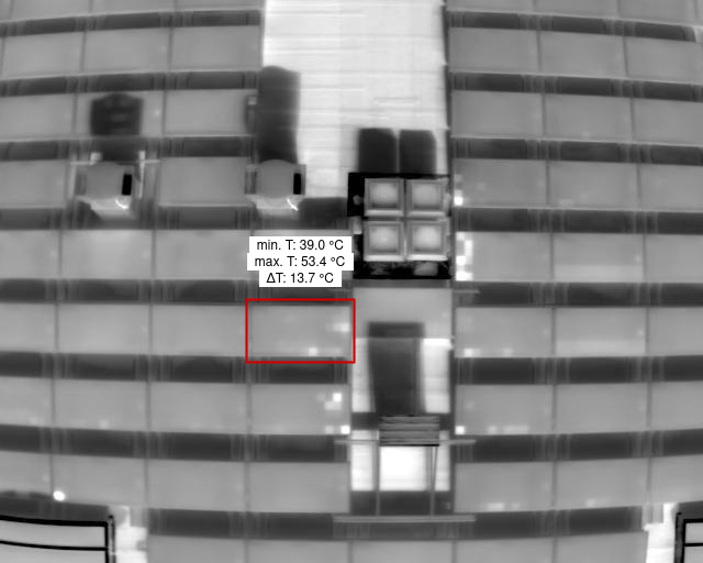
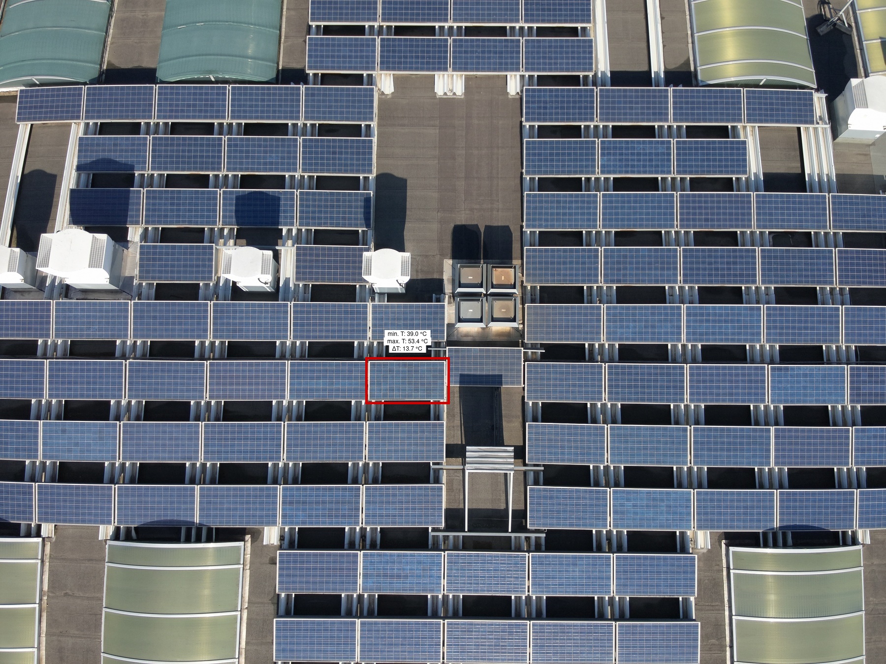
Cell Multi Medium |
1 | 82A | 1 | 1 | 6 | 1 | Low | 13.7 | |
|
|
Diode |
1 | 83C | 1 | 1 | 1 | 1 | Medium | 3.6 | |
|

|
Module |
1 | 52A | 1 | 1 | 5 | 1 | High | ||

|
|
Soiling |
1 | 80C | 1 | 1 | 1 | 1 | Low | ||

|

|
Diode |
1 | 82B | 1 | 1 | 2 | 1 | Medium | 5.5 | |
|
|
Module |
1 | 50B | 1 | 1 | 7 | 1 | High | ||
|
|
Module |
1 | 49C | 1 | 1 | 6 | 1 | High | ||
|
|
Cell Low |
1 | 42A | 1 | 1 | 4 | 1 | Low | 6.1 | |
|
|
Module |
1 | 53A | 1 | 1 | 2 | 1 | High | ||
|
|
Diode |
1 | 81B | 1 | 1 | 2 | 1 | Medium | 6.1 | |
|

|
Module |
1 | 64 | 1 | 1 | 3 | 1 | High | ||

|
|
Soiling |
1 | 81B | 1 | 1 | 1 | 1 | Low | ||
|

|
Module |
1 | 51B | 1 | 1 | 8 | 1 | High | ||
|
|
Module |
1 | 49B | 1 | 1 | 8 | 1 | High | ||
|
|
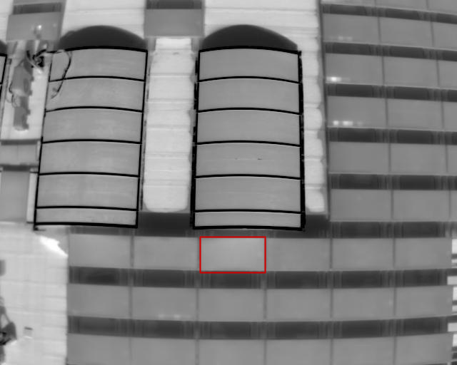
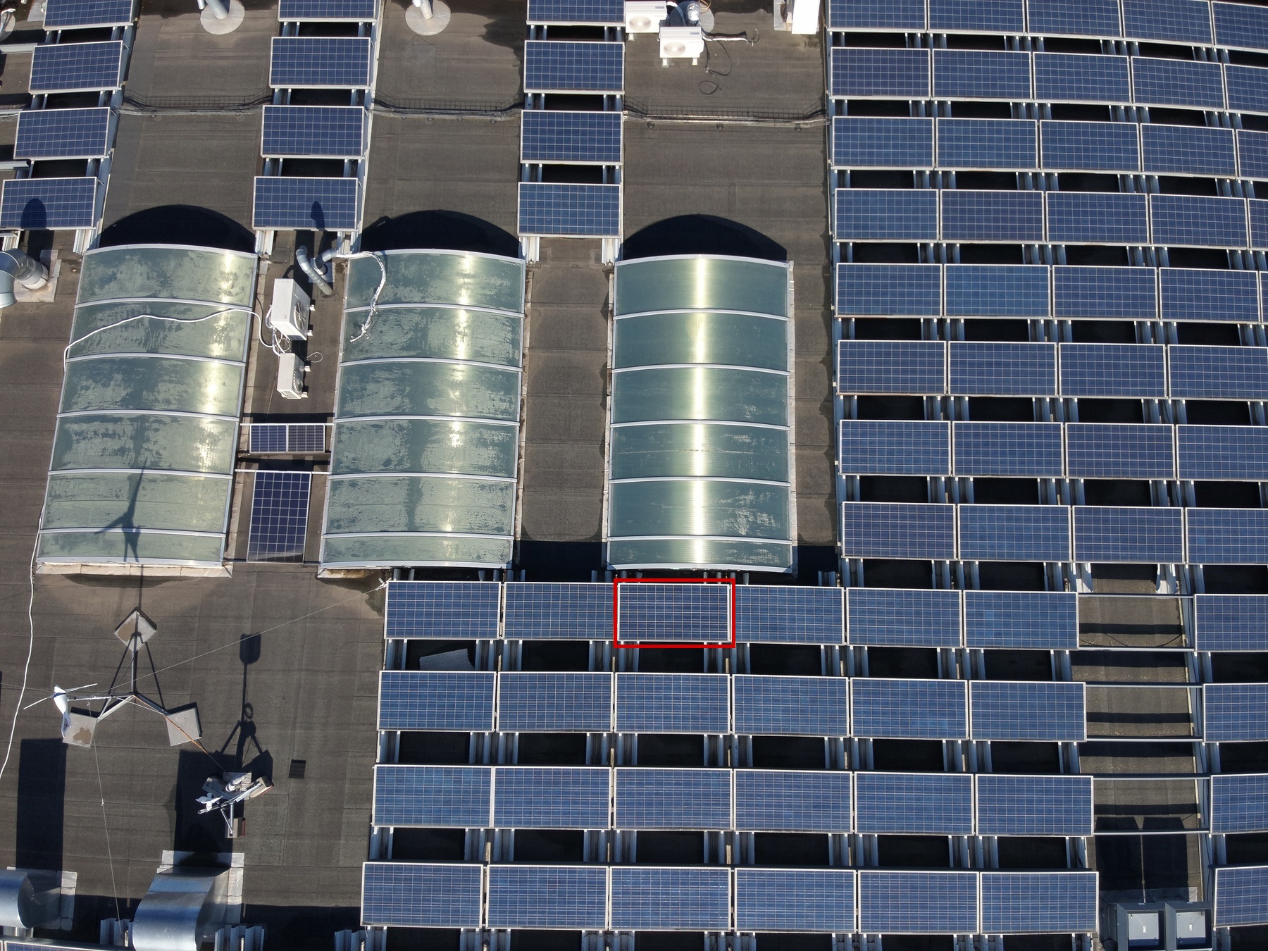
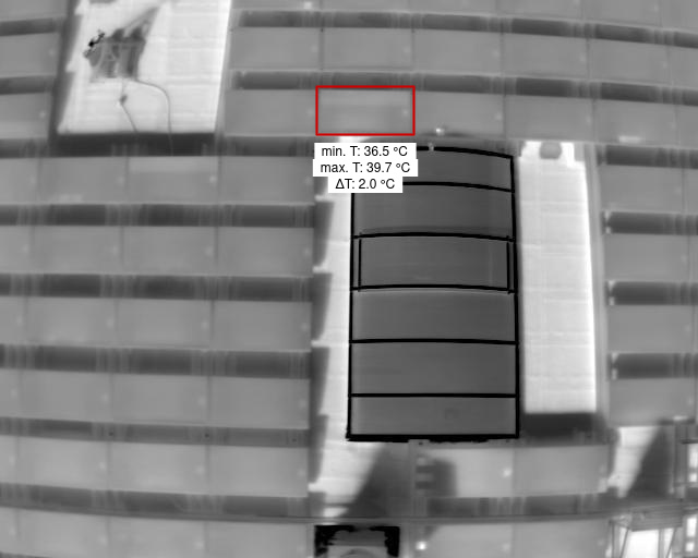
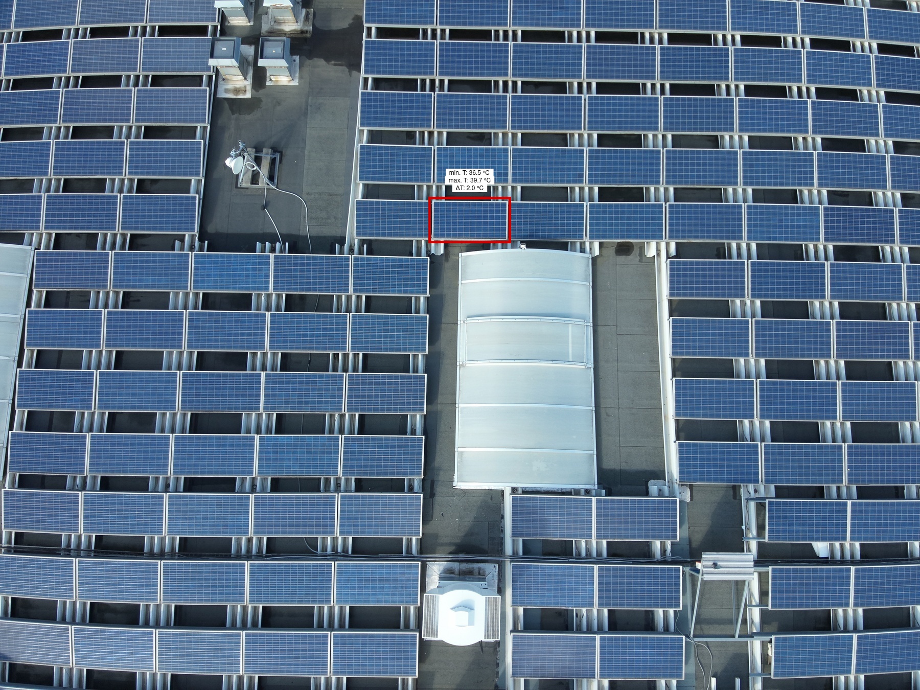
Diode |
1 | 70C | 1 | 1 | 1 | 1 | Medium | 4.4 | |
|

|
Module |
1 | 49B | 1 | 1 | 9 | 1 | High | ||
|
|
Module |
1 | 49B | 1 | 1 | 10 | 1 | High | ||
|

|
Module |
1 | 48C | 1 | 1 | 2 | 1 | High | ||
|

|
Module |
1 | 49C | 1 | 1 | 5 | 1 | High | ||
|

|
Module |
1 | 50B | 1 | 1 | 8 | 1 | High | ||
|
|
Module |
1 | 51B | 1 | 1 | 9 | 1 | High | ||
|

|
Module |
1 | 63 | 1 | 1 | 3 | 1 | High | ||
|
|
Diode |
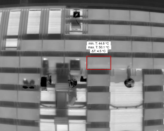
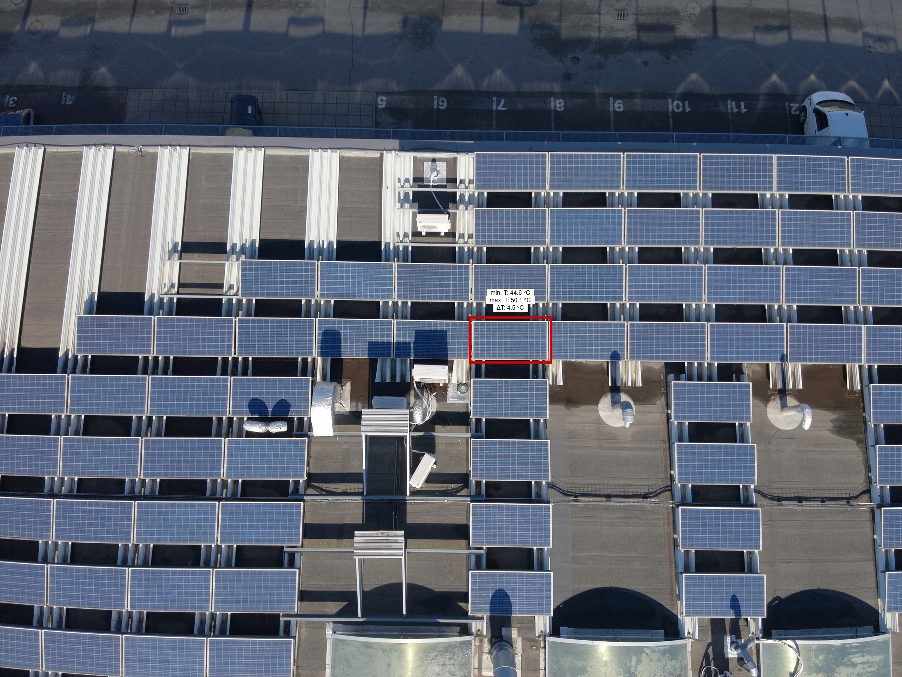
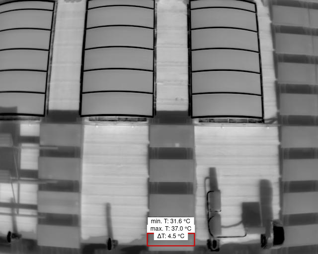
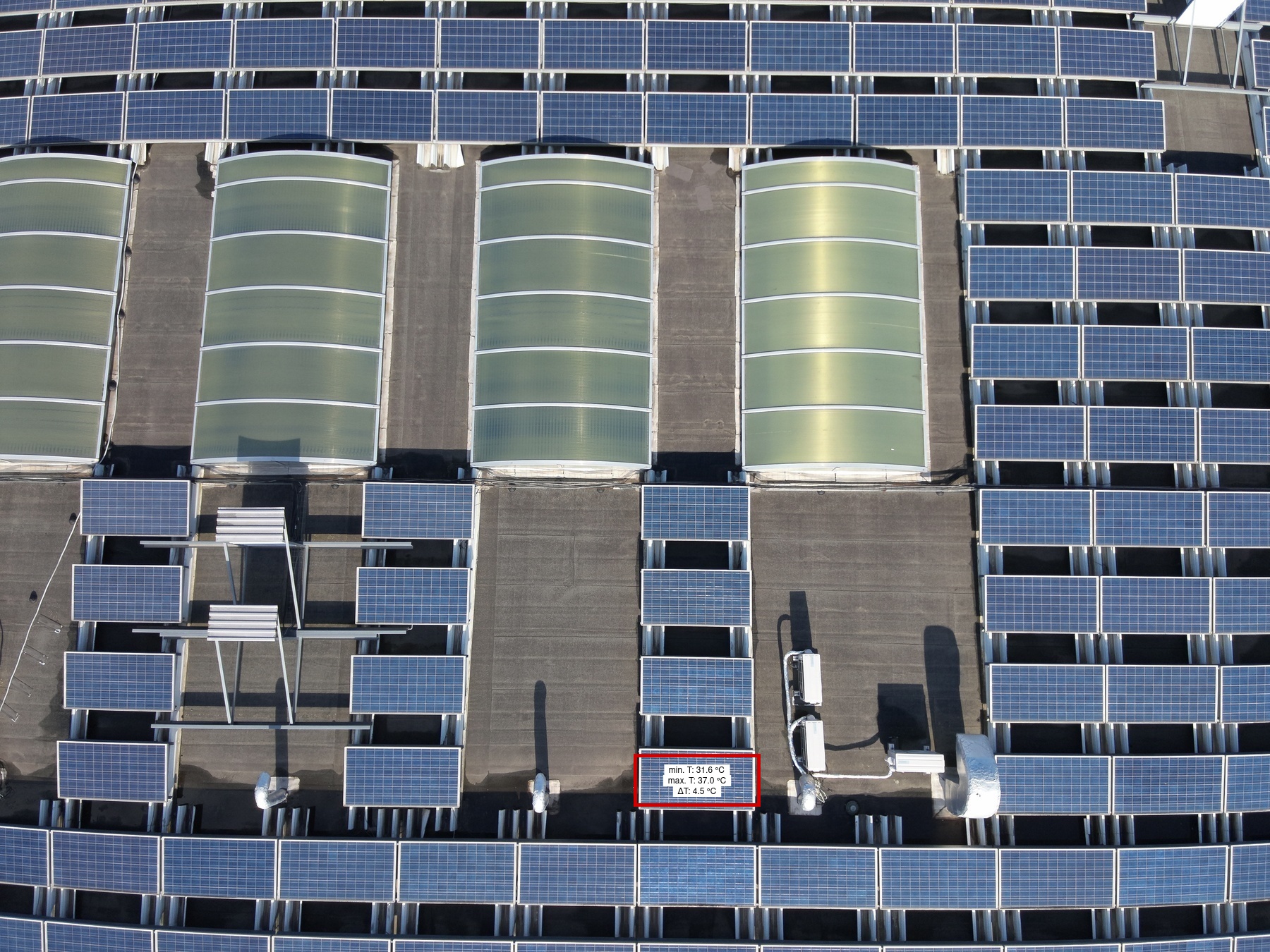
1 | 41A | 1 | 1 | 4 | 1 | Medium | 4.5 | |
|
|
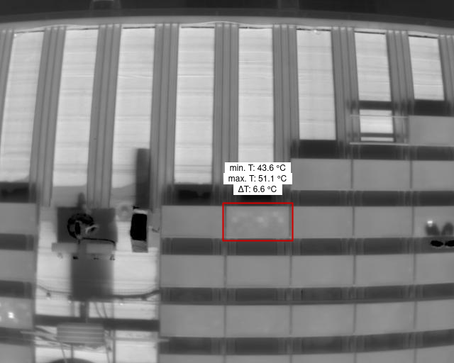
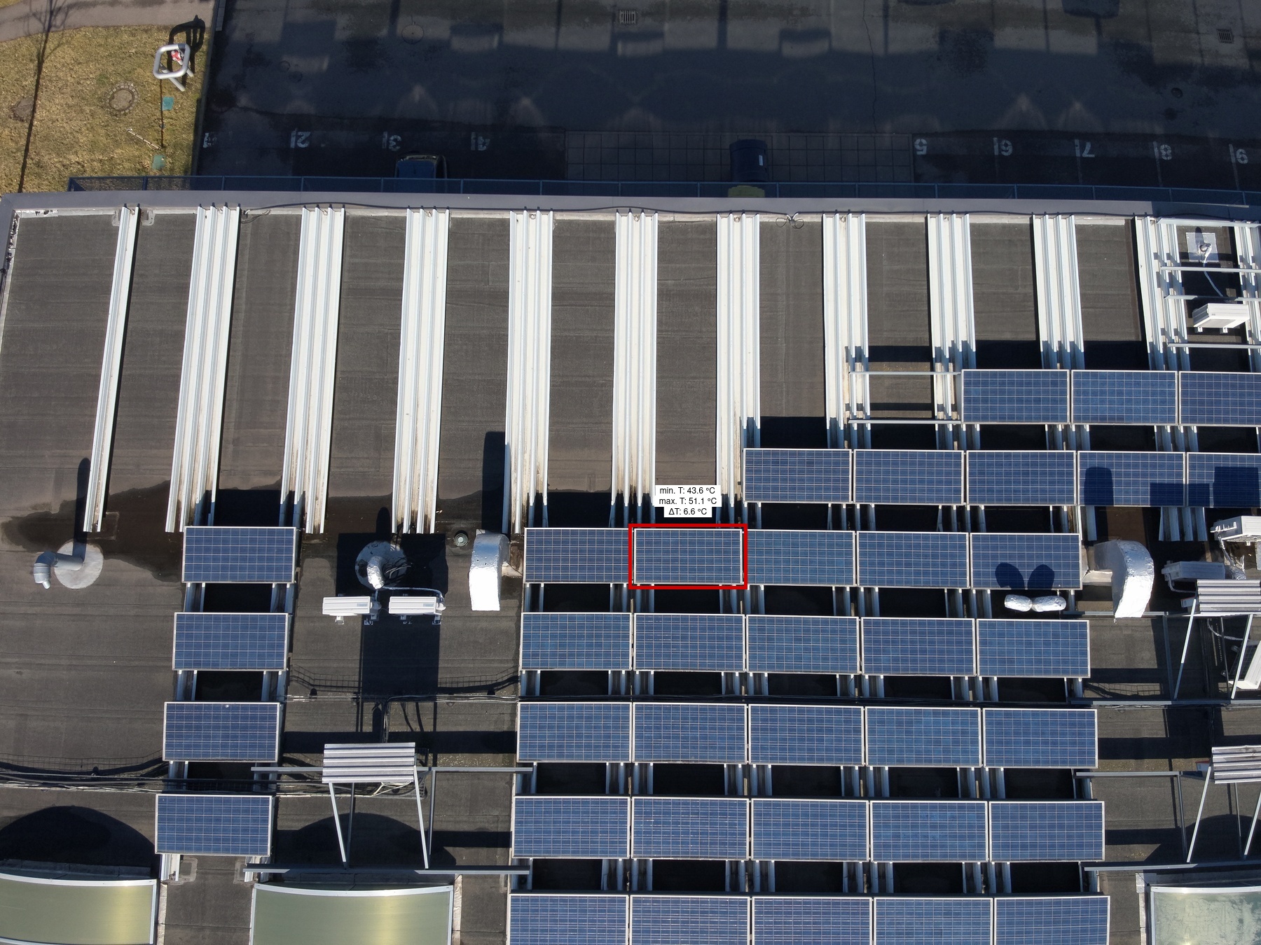
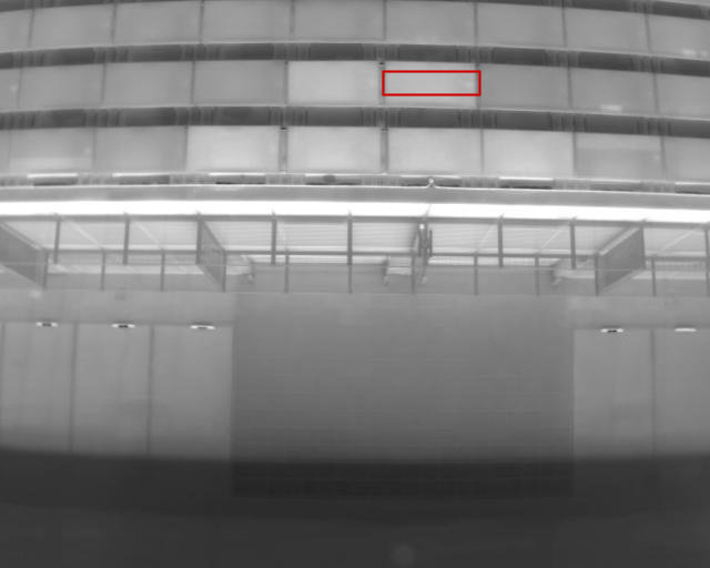
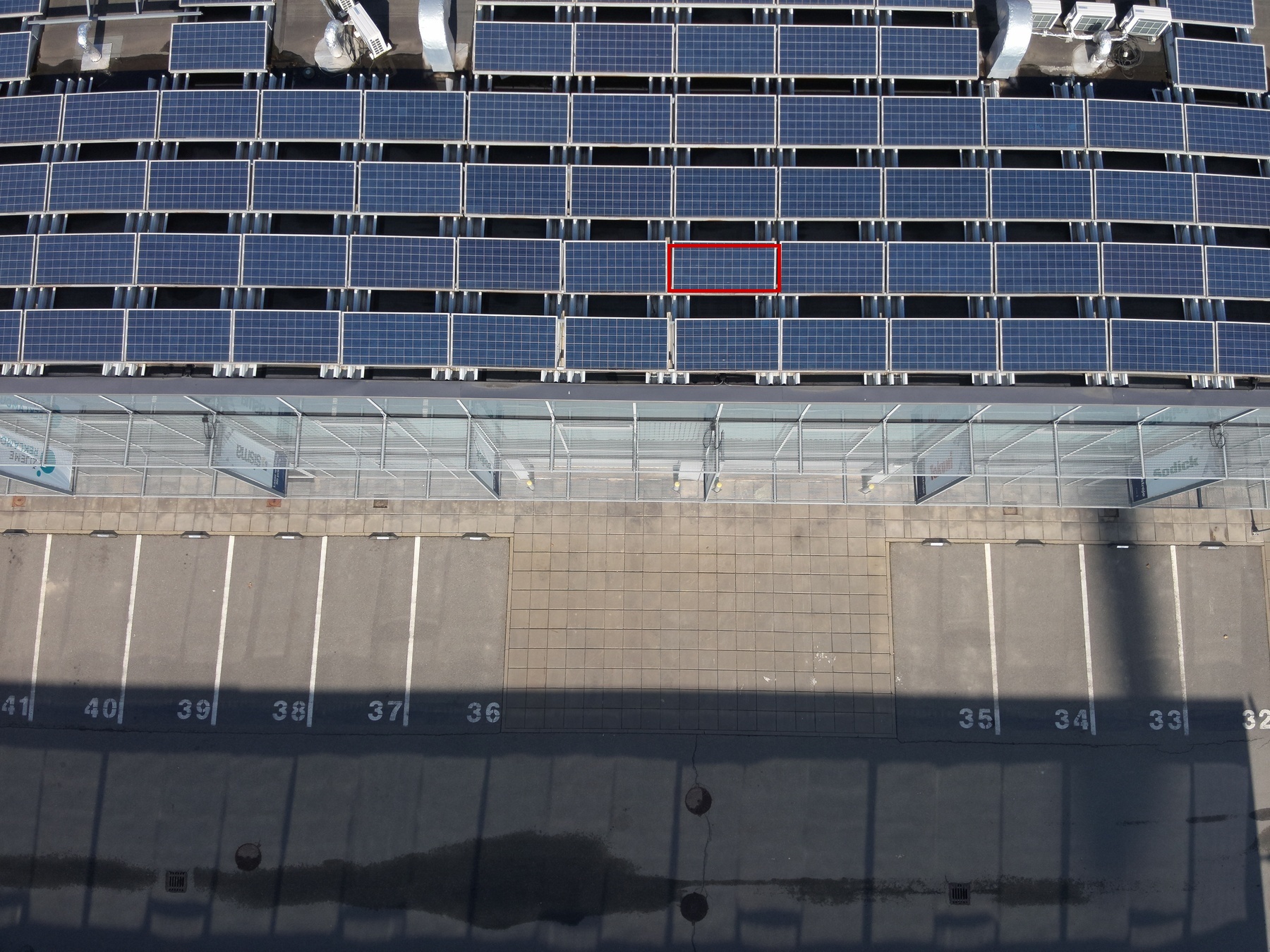
Cell Multi Low |
1 | 37B | 1 | 1 | 2 | 1 | Low | 6.6 | |
|
|
Module |
1 | 63 | 1 | 1 | 22 | 1 | High | ||
|
|
Module |
1 | 53B | 1 | 1 | 1 | 1 | High | ||
|
|
Module |
1 | 54B | 1 | 1 | 1 | 1 | High | ||
|

|
Module |
1 | 50C | 1 | 1 | 6 | 1 | High | ||
|

|
Module |
1 | 45A | 1 | 1 | 1 | 1 | High | ||
|
|
Module |
1 | 63 | 1 | 1 | 10 | 1 | High | ||
|
|
Module |
1 | 53B | 1 | 1 | 2 | 1 | High | ||
|
|
Diode |
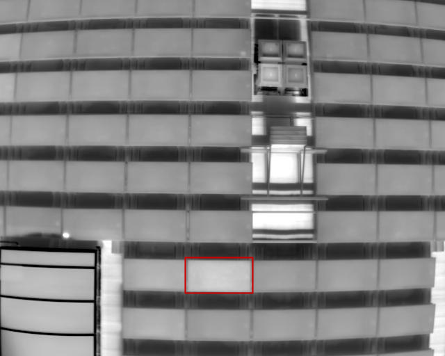
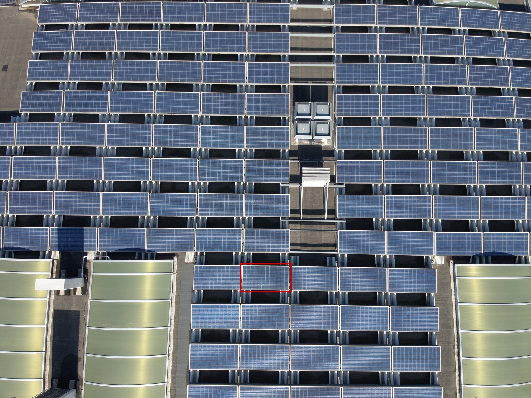
1 | 70D | 1 | 1 | 1 | 1 | Medium | 6.4 | |
|
|
Module |
1 | 63 | 1 | 1 | 5 | 1 | High | ||
|
|
Diode |
1 | 67C | 1 | 1 | 11 | 1 | Medium | 5.2 | |

|

|
Module |
1 | 64 | 1 | 1 | 5 | 1 | High | ||
|
|
Module |
1 | 64 | 1 | 1 | 23 | 1 | High | ||
|
|
Module |
1 | 58F | 1 | 1 | 4 | 1 | High | ||
|
|
Diode |
1 | 42B | 1 | 1 | 4 | 1 | Medium | 4.4 | |
|
|
Module |
1 | 45C | 1 | 1 | 3 | 1 | High | ||
|
|
Cell Low |
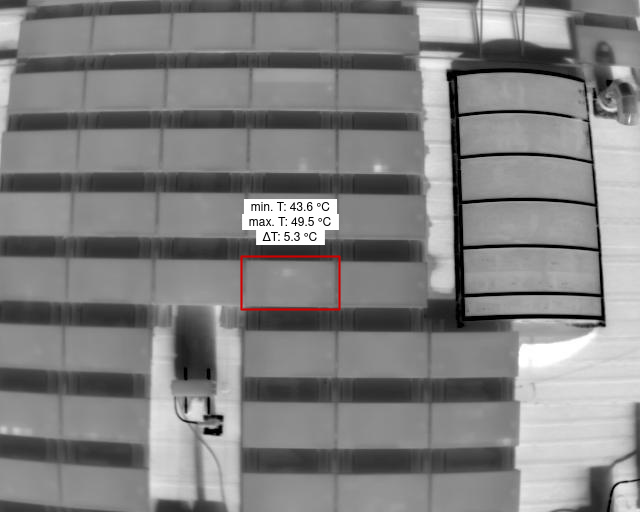
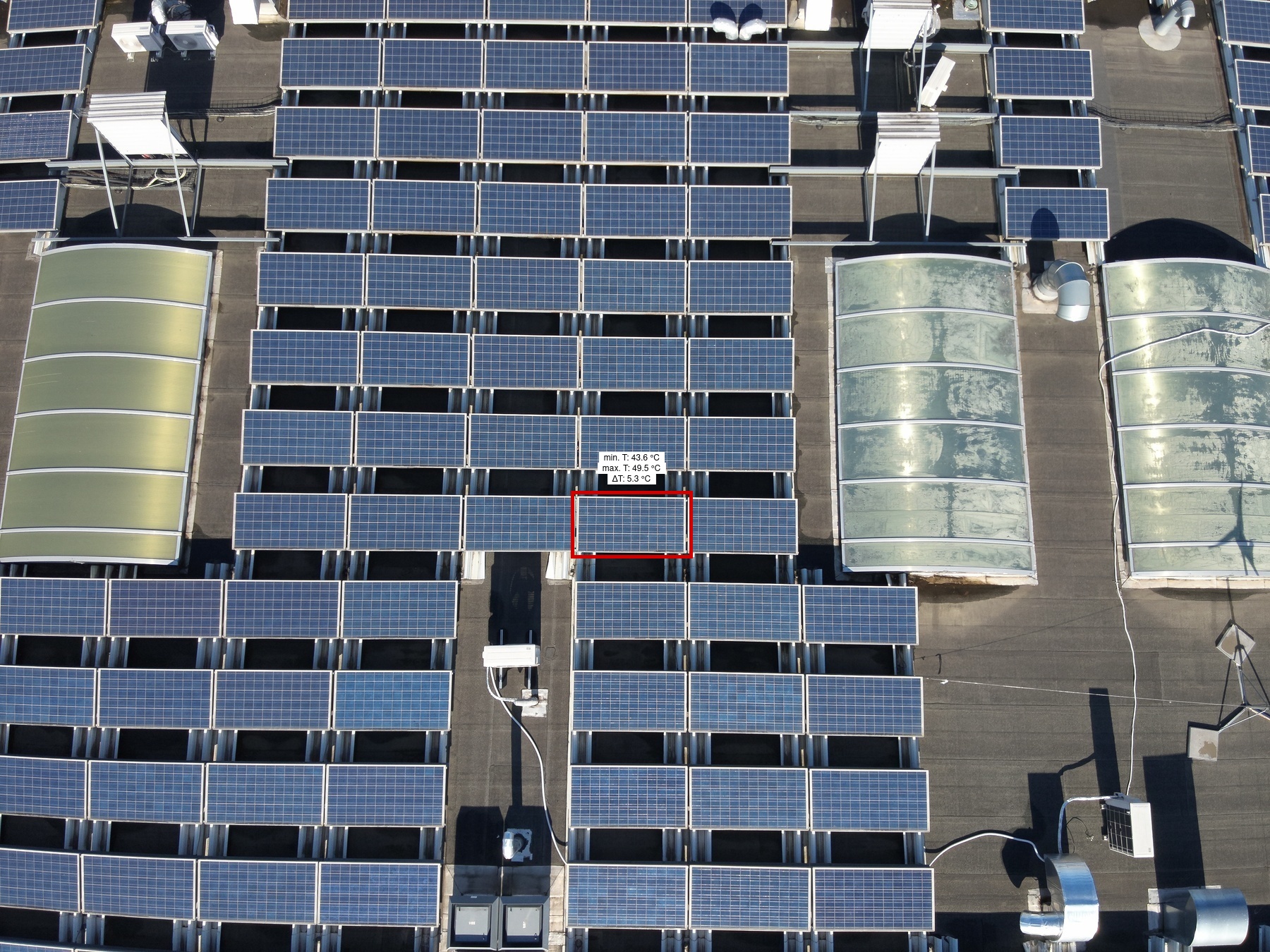
1 | 44A | 1 | 1 | 4 | 1 | Low | 5.3 | |
|

|
Module |
1 | 63 | 1 | 1 | 4 | 1 | High | ||
|
|
Module |
1 | 45A | 1 | 1 | 3 | 1 | High | ||
|
|
Module |
1 | 64 | 1 | 1 | 4 | 1 | High | ||
|
|
Internal Short Circuit High |
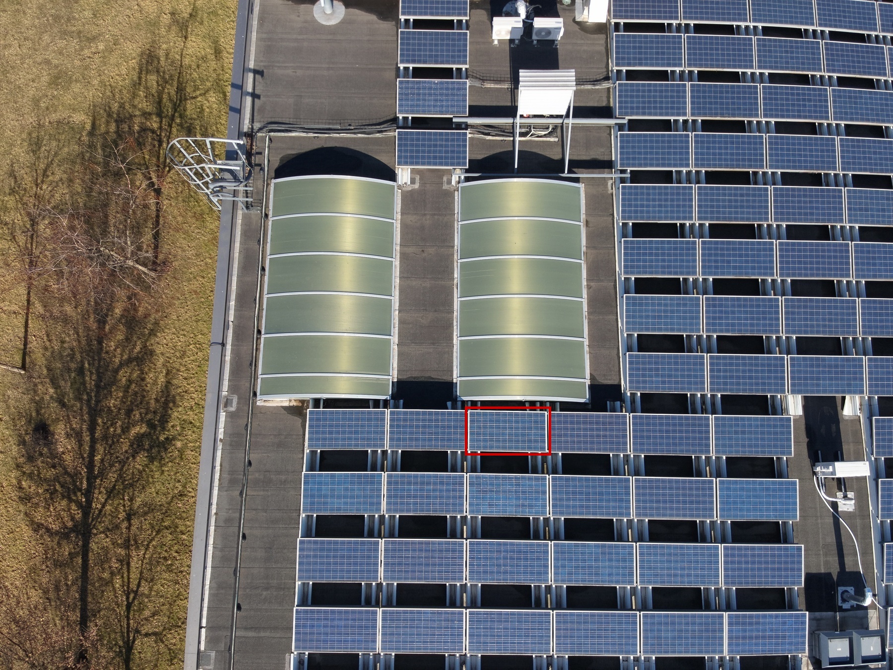
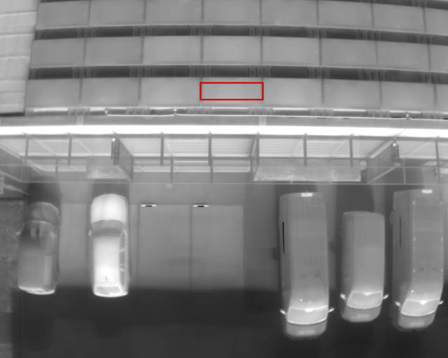
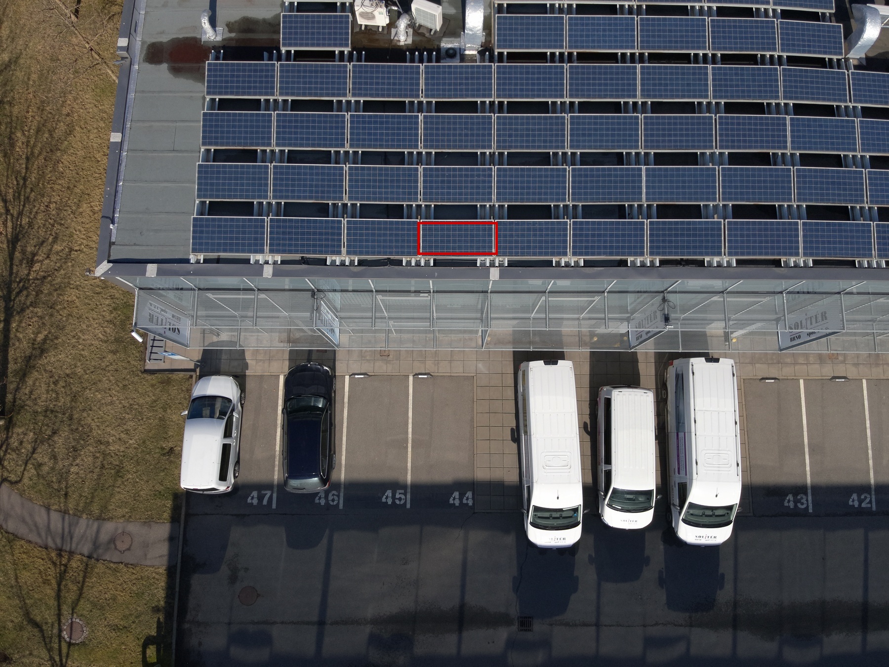
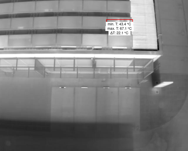
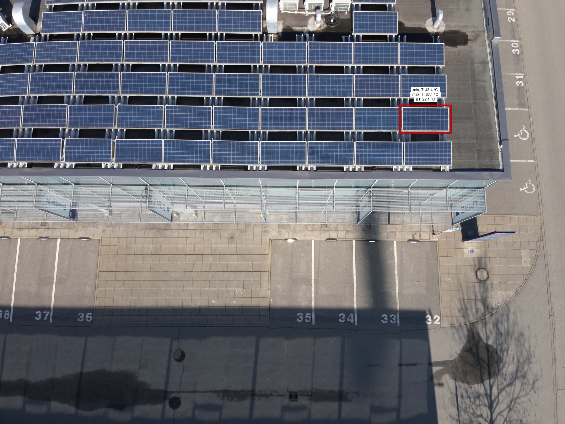
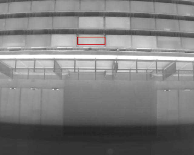
1 | 63 | 1 | 1 | 28 | 1 | Low | 22.1 | |
|

|
Module |
1 | 64 | 1 | 1 | 21 | 1 | High | ||
|

|
Module |
1 | 46A | 1 | 1 | 2 | 1 | High | ||
|

|
Module |
1 | 63 | 1 | 1 | 11 | 1 | High | ||
|

|
Module |
1 | 46A | 1 | 1 | 1 | 1 | High | ||
|
|
Module |
1 | 64 | 1 | 1 | 28 | 1 | High | ||
|
|
Module |
1 | 64 | 1 | 1 | 10 | 1 | High | ||
|
|
Diode |
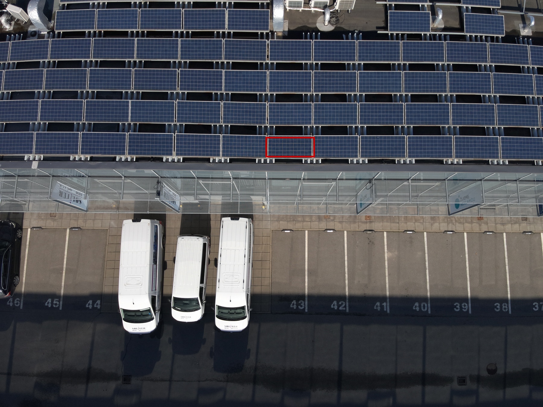
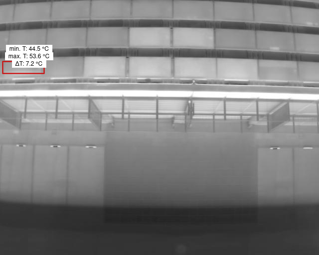
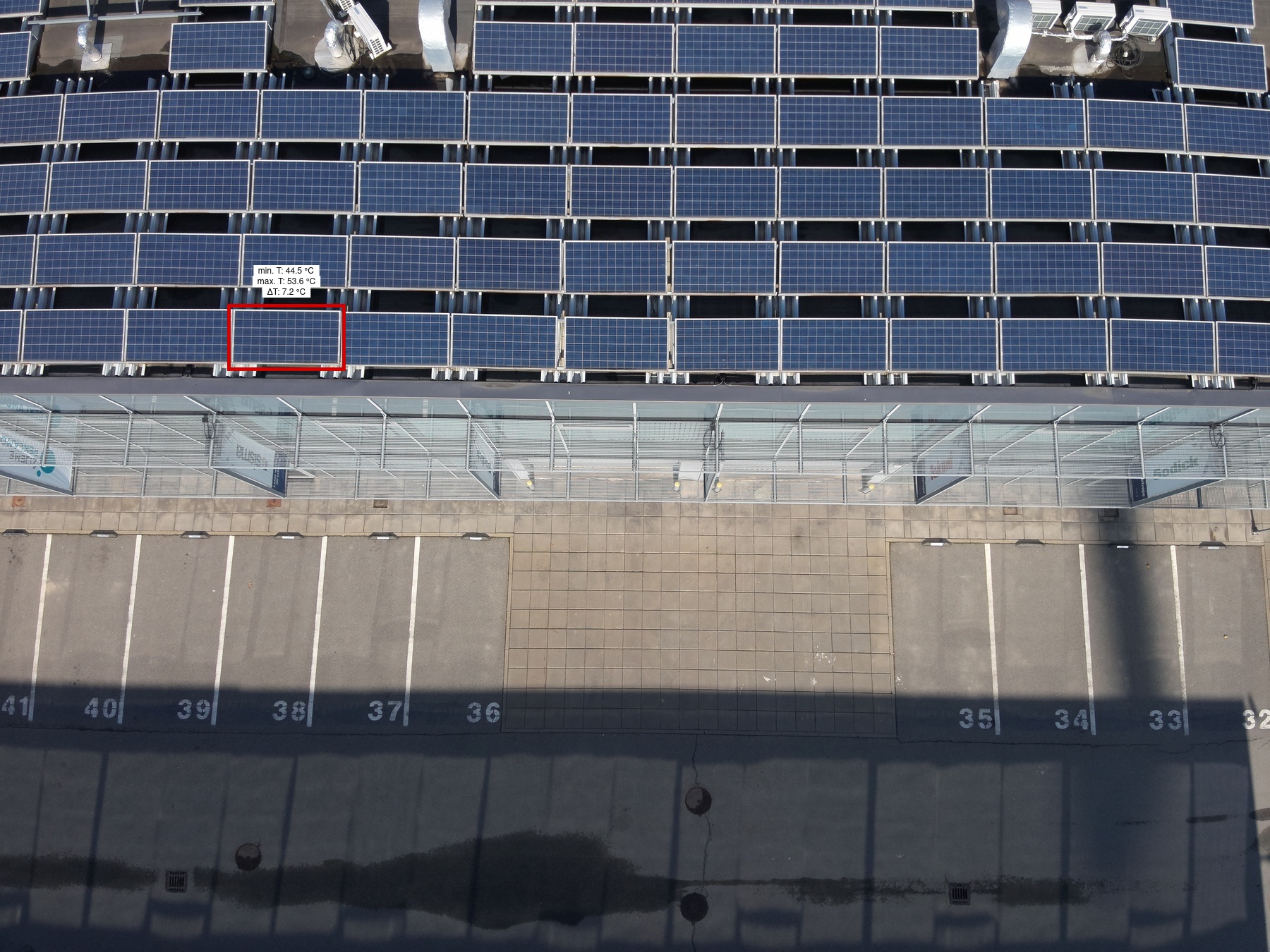
1 | 64 | 1 | 1 | 18 | 1 | Medium | 7.2 | |
|
|
Cracking |
1 | 39A | 1 | 1 | 1 | 1 | High | ||

|
|
Module |
1 | 64 | 1 | 1 | 27 | 1 | High | ||
|

|
Module |
1 | 64 | 1 | 1 | 22 | 1 | High | ||
|
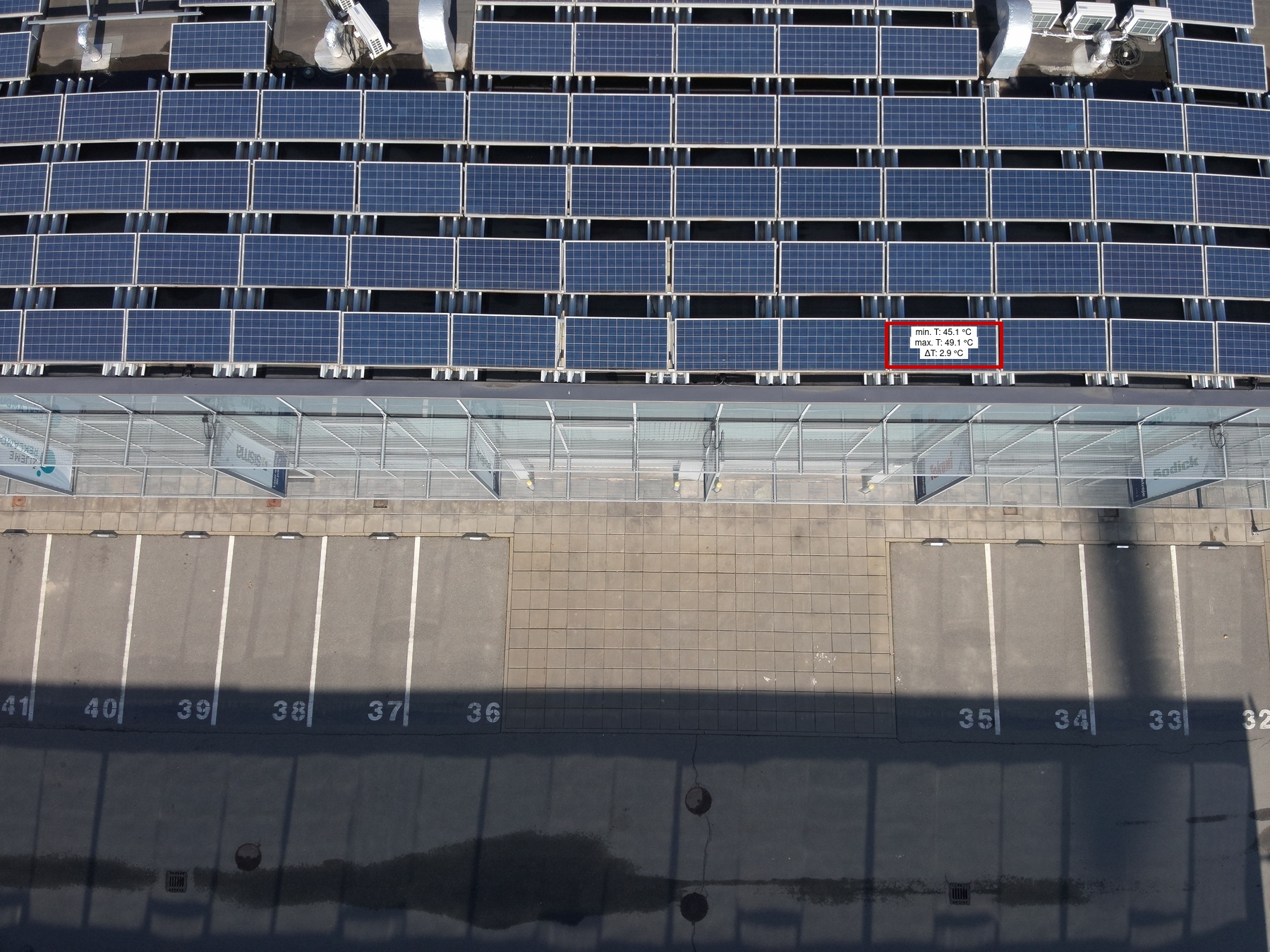
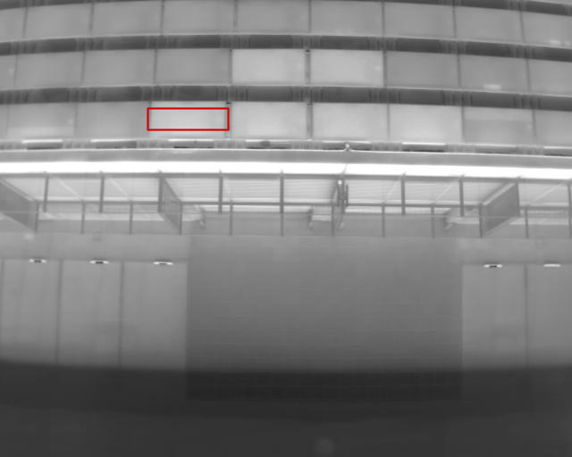
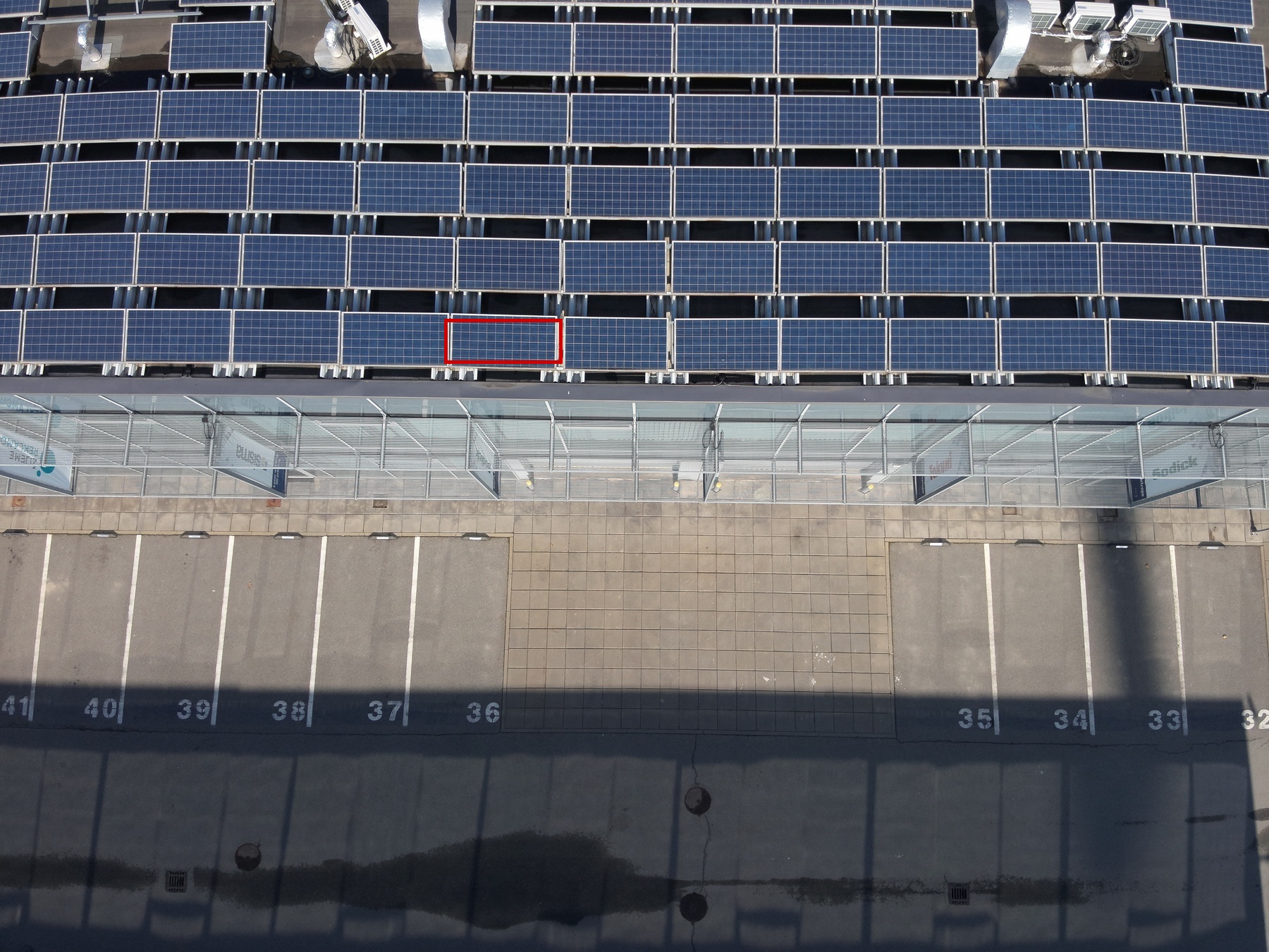
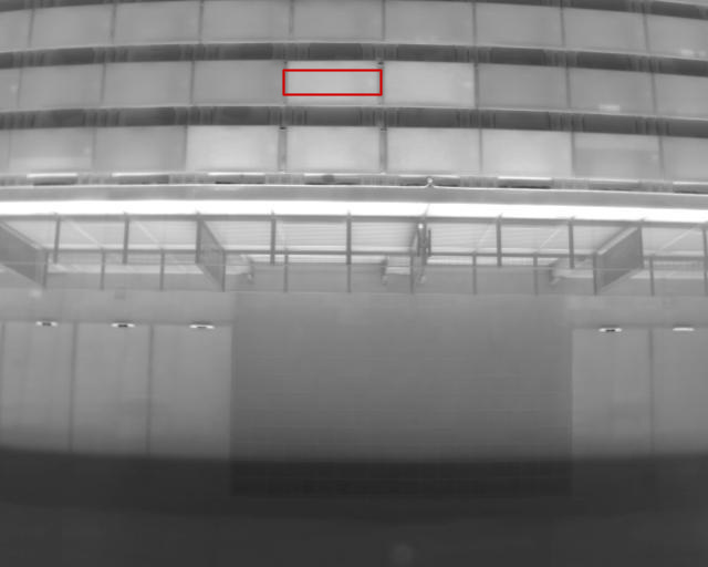
|
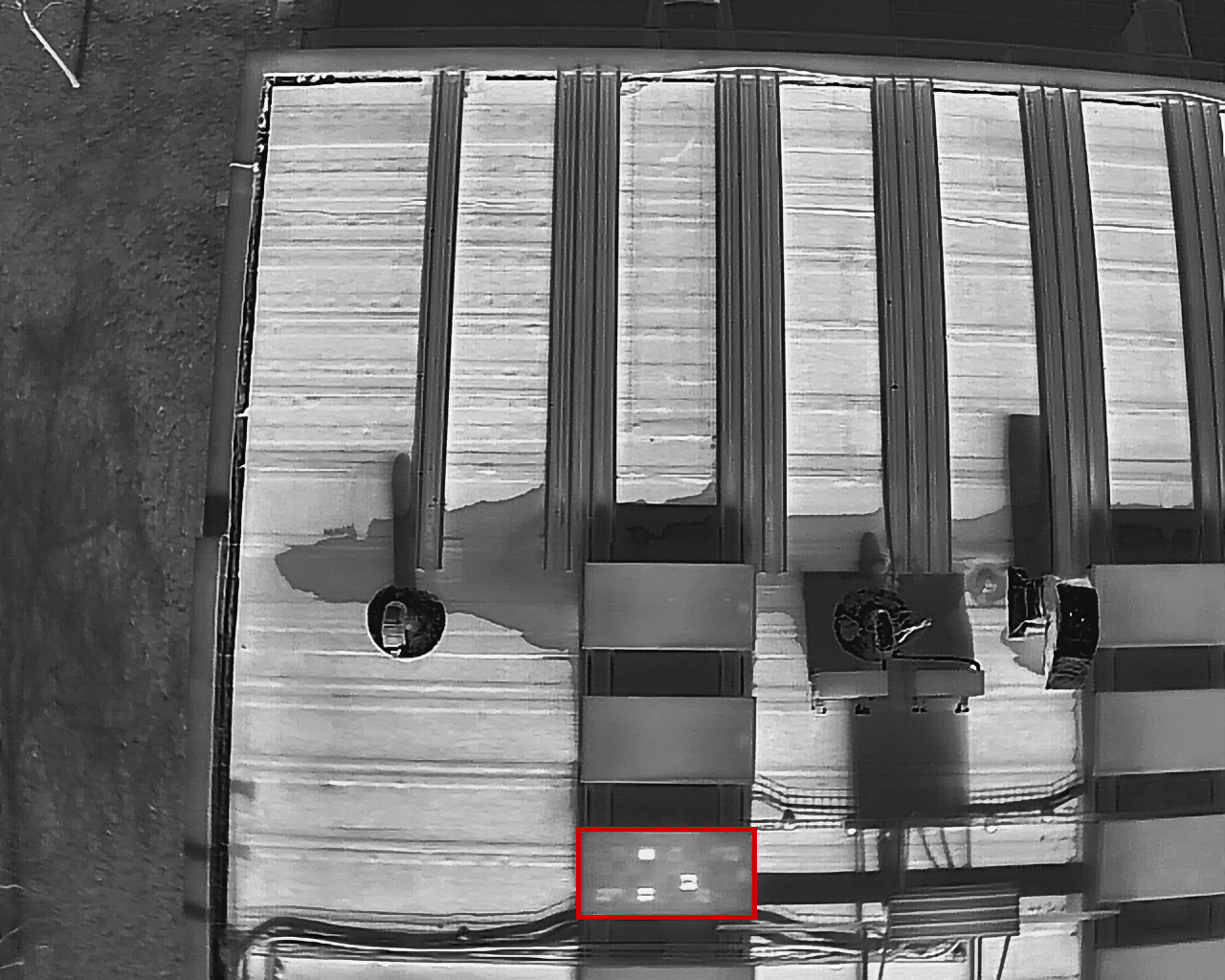
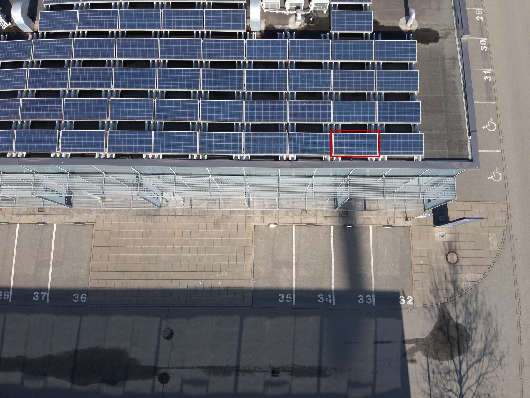
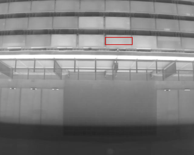
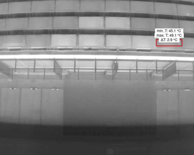
Diode |
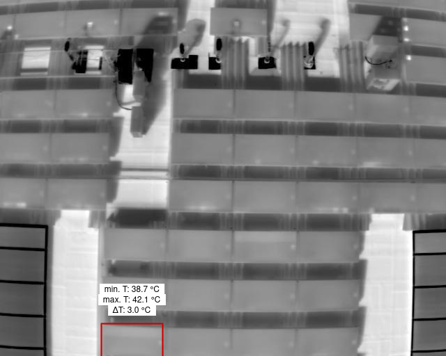
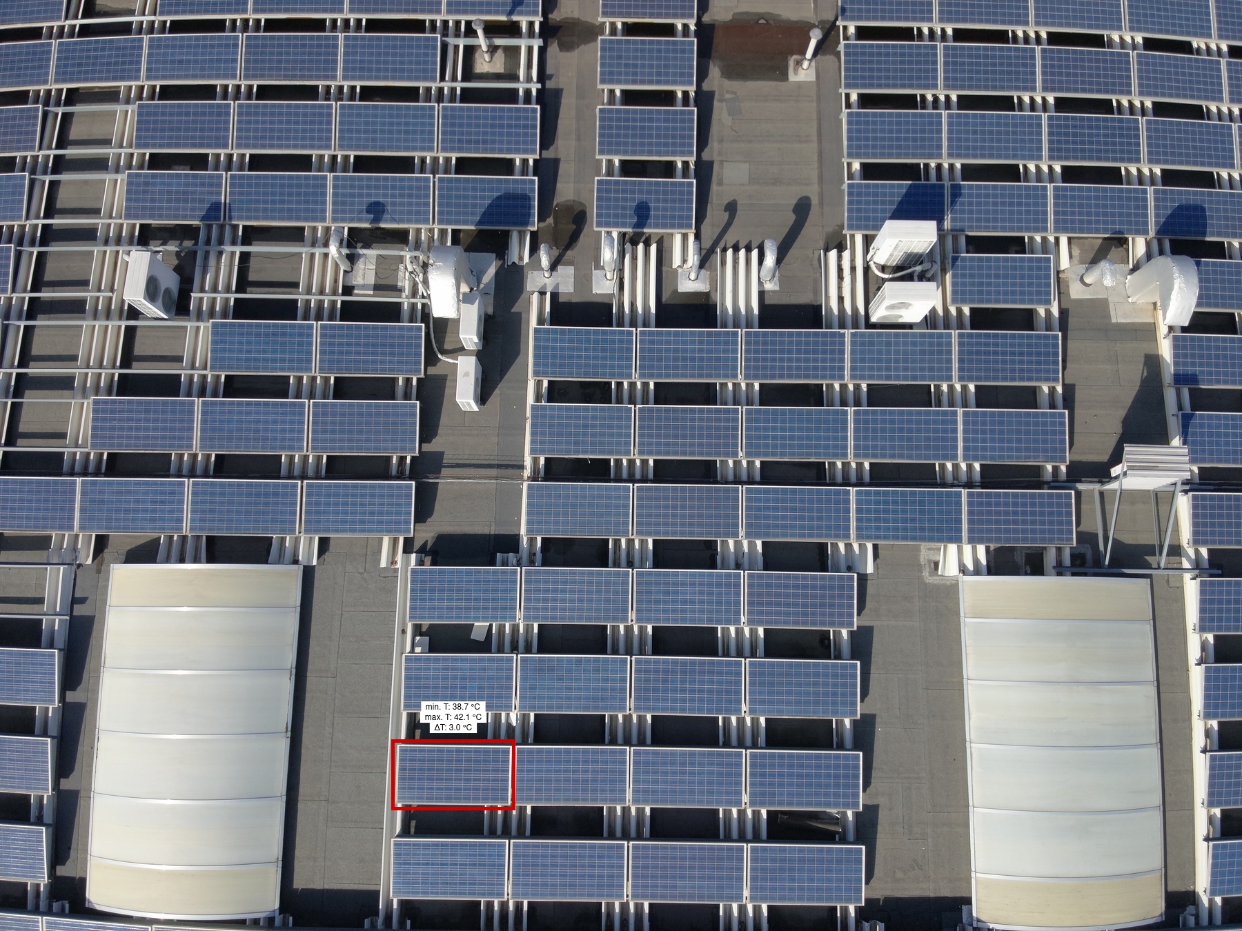
1 | 64 | 1 | 1 | 24 | 1 | Medium | 2.9 | |
|
|
Module |
1 | 64 | 1 | 1 | 20 | 1 | High | ||
|
|
Module |
1 | 63 | 1 | 1 | 21 | 1 | High | ||
|

|
Module |
1 | 49A | 1 | 1 | 1 | 1 | High | ||
|
|
Module |
1 | 49A | 1 | 1 | 2 | 1 | High | ||
|
|
Diode |
1 | 36 | 1 | 1 | 6 | 1 | Medium | 4.5 | |
|
|
Module |
1 | 48A | 1 | 1 | 1 | 1 | High | ||
|
|
Module |
1 | 58F | 1 | 1 | 3 | 1 | High | ||
|
|
Diode |
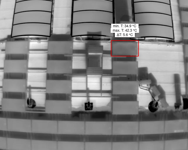
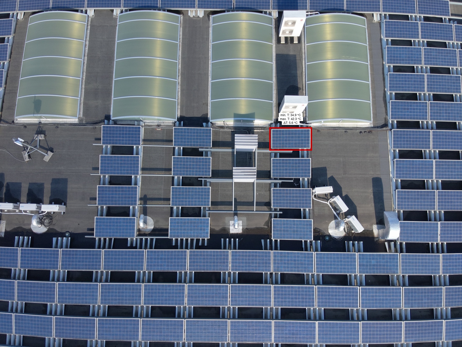
1 | 57E | 1 | 1 | 1 | 1 | Medium | 5.6 | |
|
|
Module |
1 | 57F | 1 | 1 | 3 | 1 | High | ||
|
|
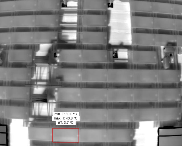
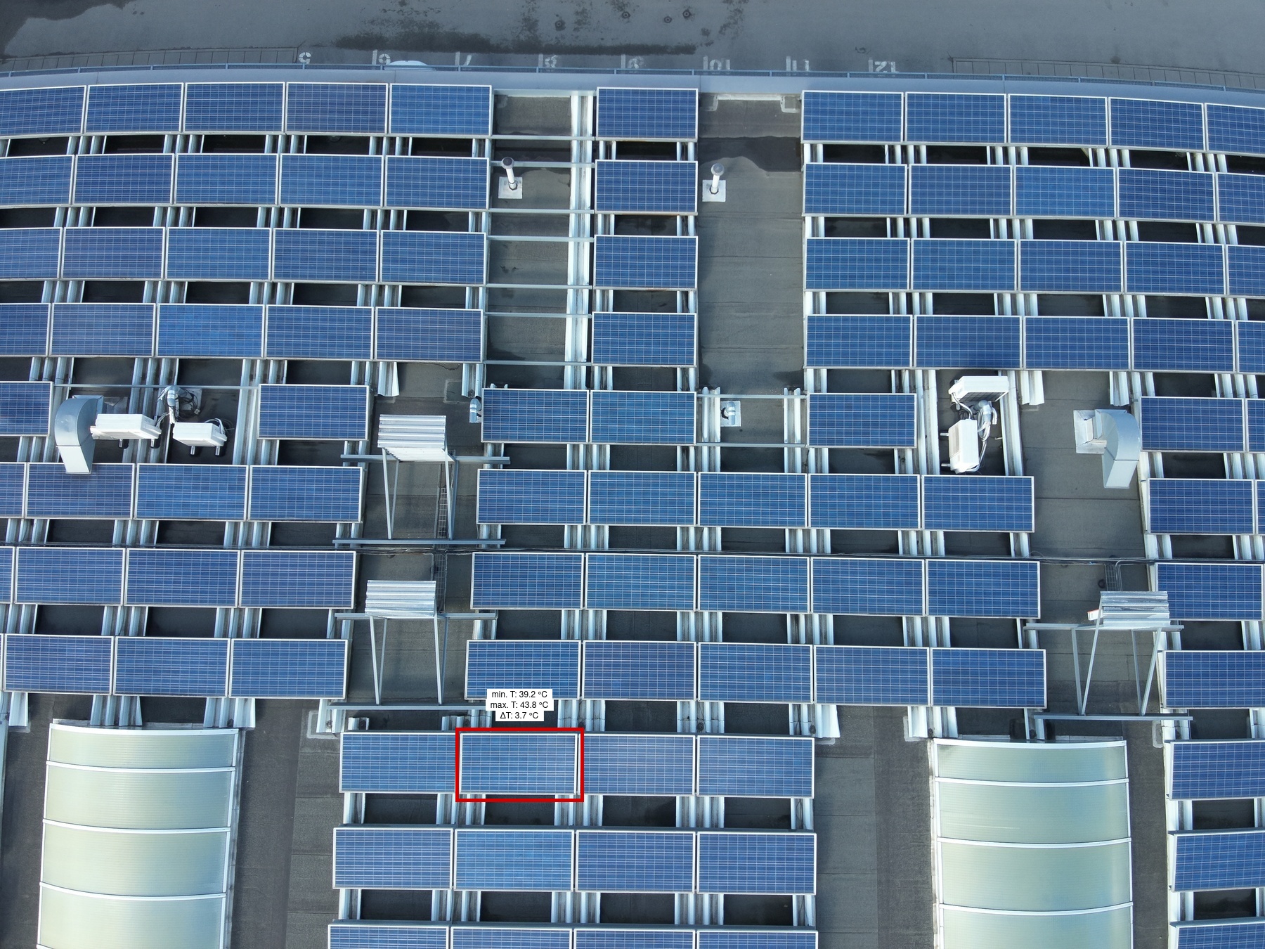
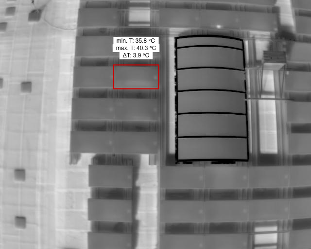
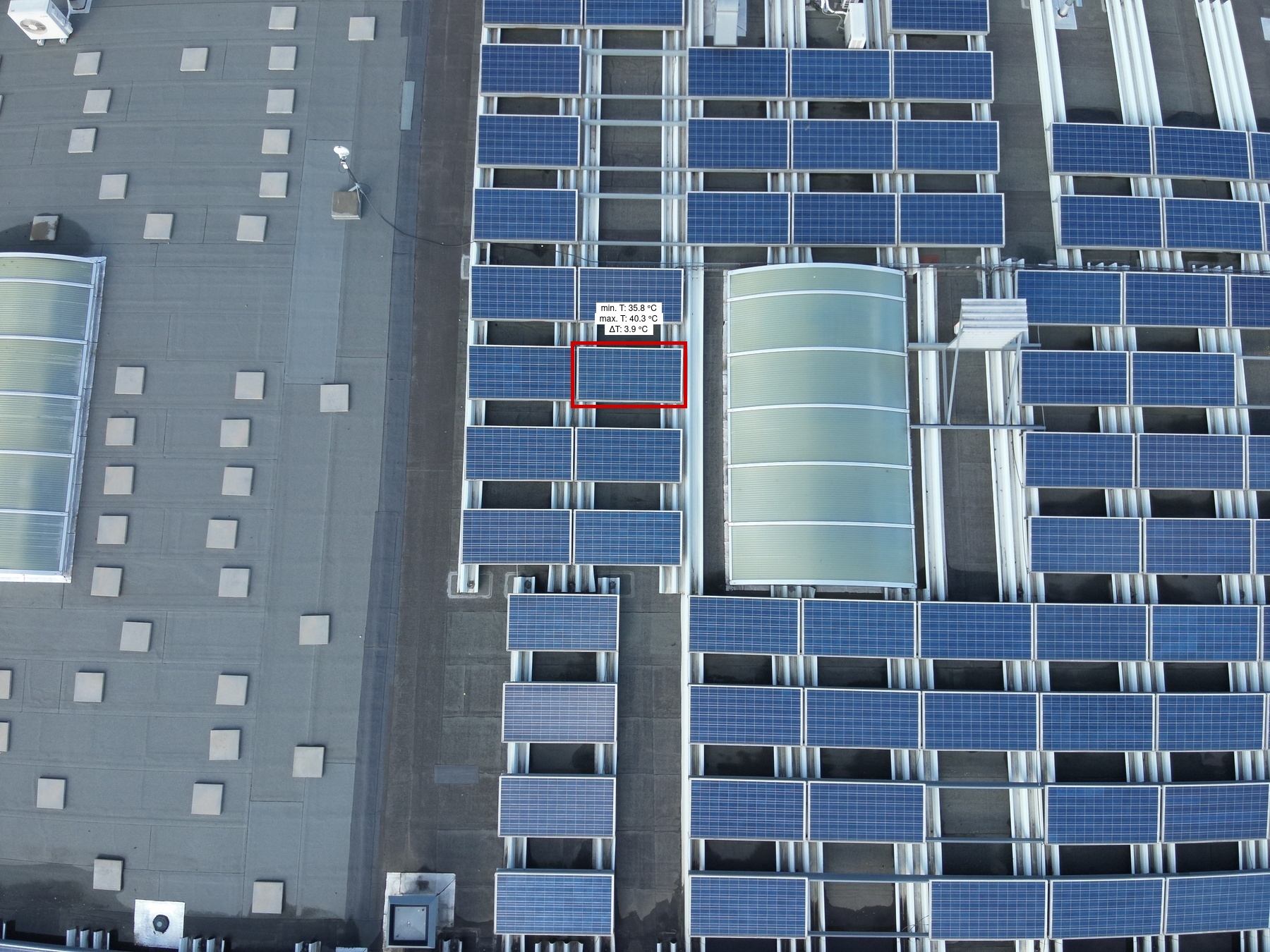
Diode |
2 | 78B | 1 | 1 | 9 | 1 | Medium | 3.7 | |
|
|
Diode |
2 | 9C | 1 | 1 | 3 | 1 | Medium | 3.6 | |
|
|
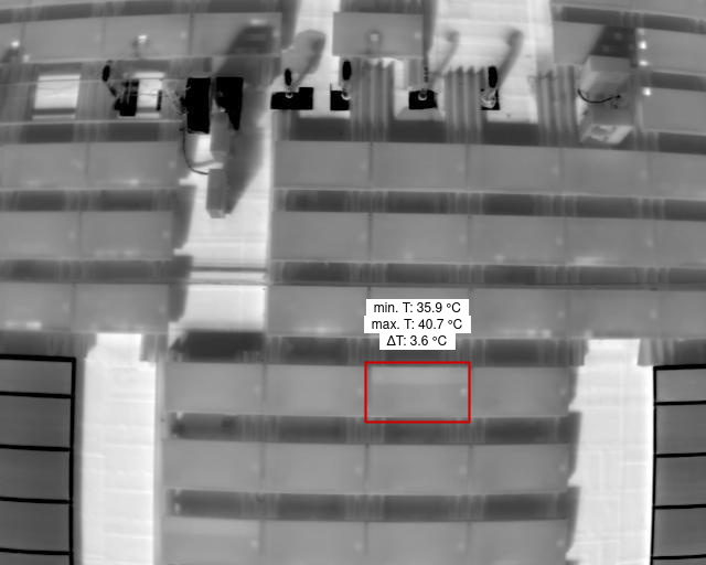
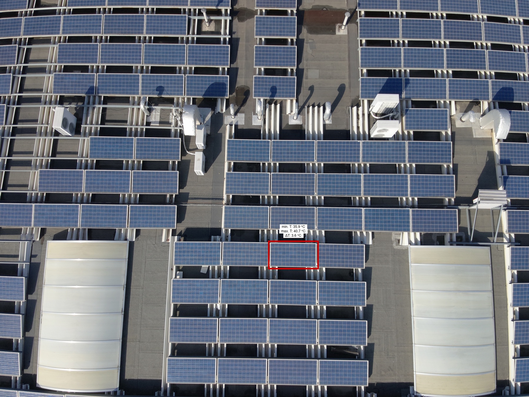
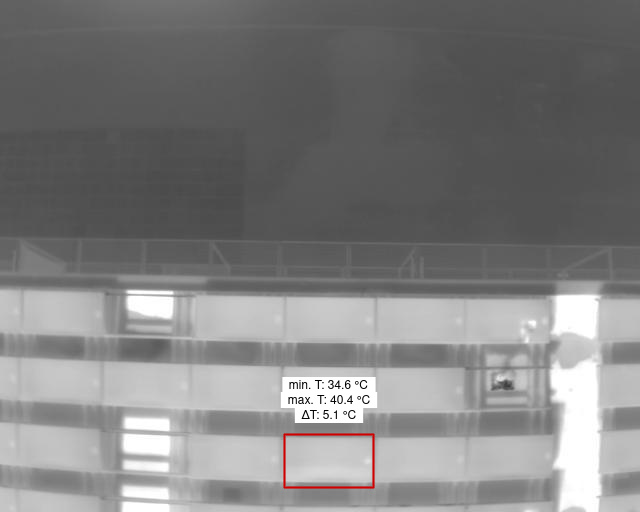
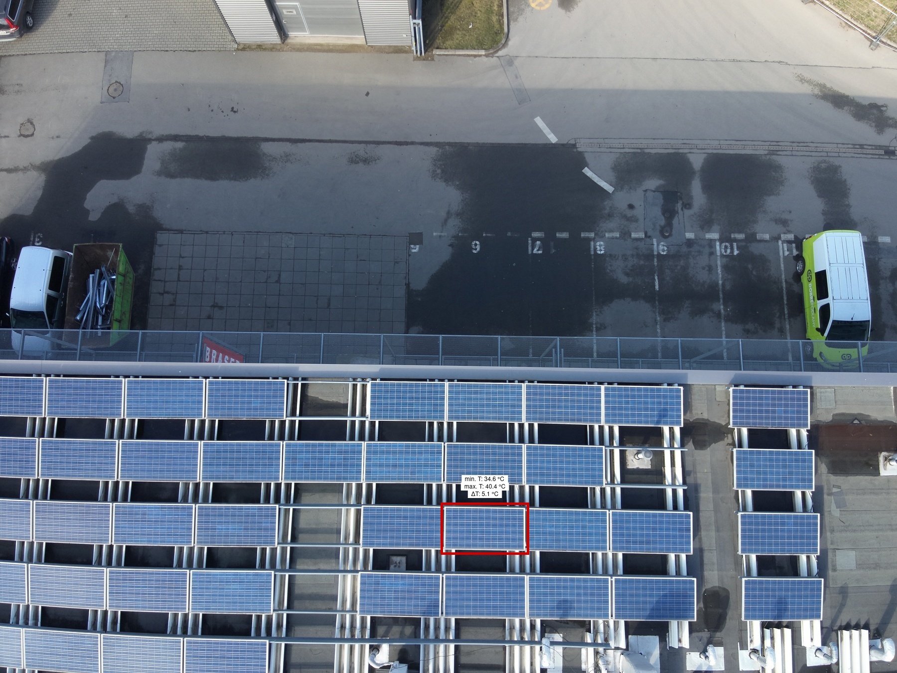
Diode |
2 | 3B | 1 | 1 | 2 | 1 | Medium | 5.1 | |
|
|
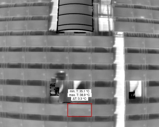
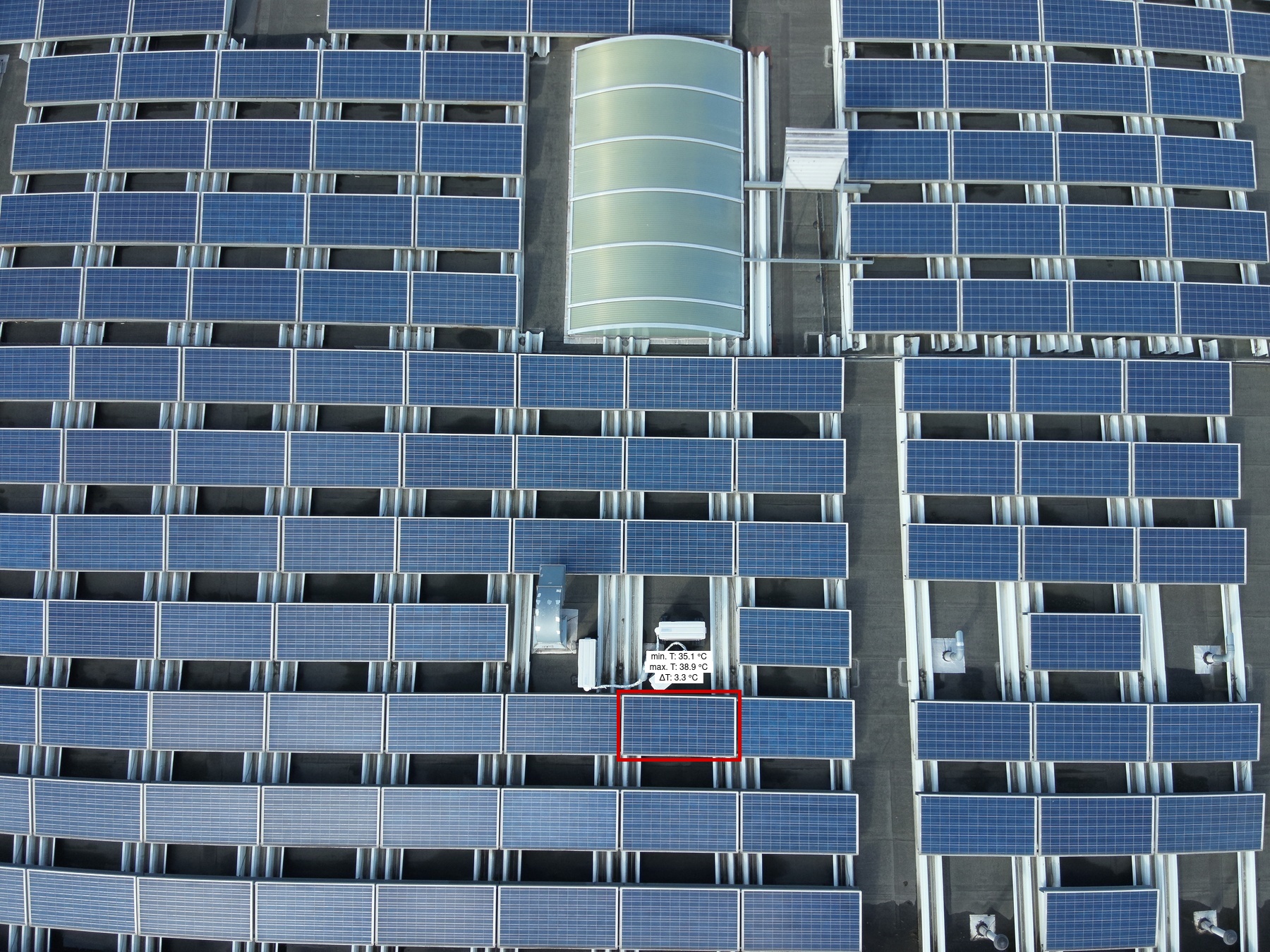
Diode |
2 | 57E | 1 | 1 | 7 | 1 | Medium | 3.3 | |
|
|
Diode |
2 | 95C | 1 | 1 | 2 | 1 | Medium | 3.9 | |
|
|
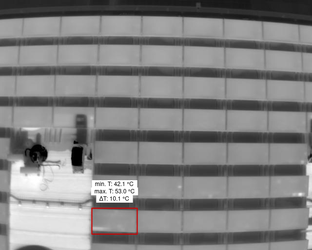
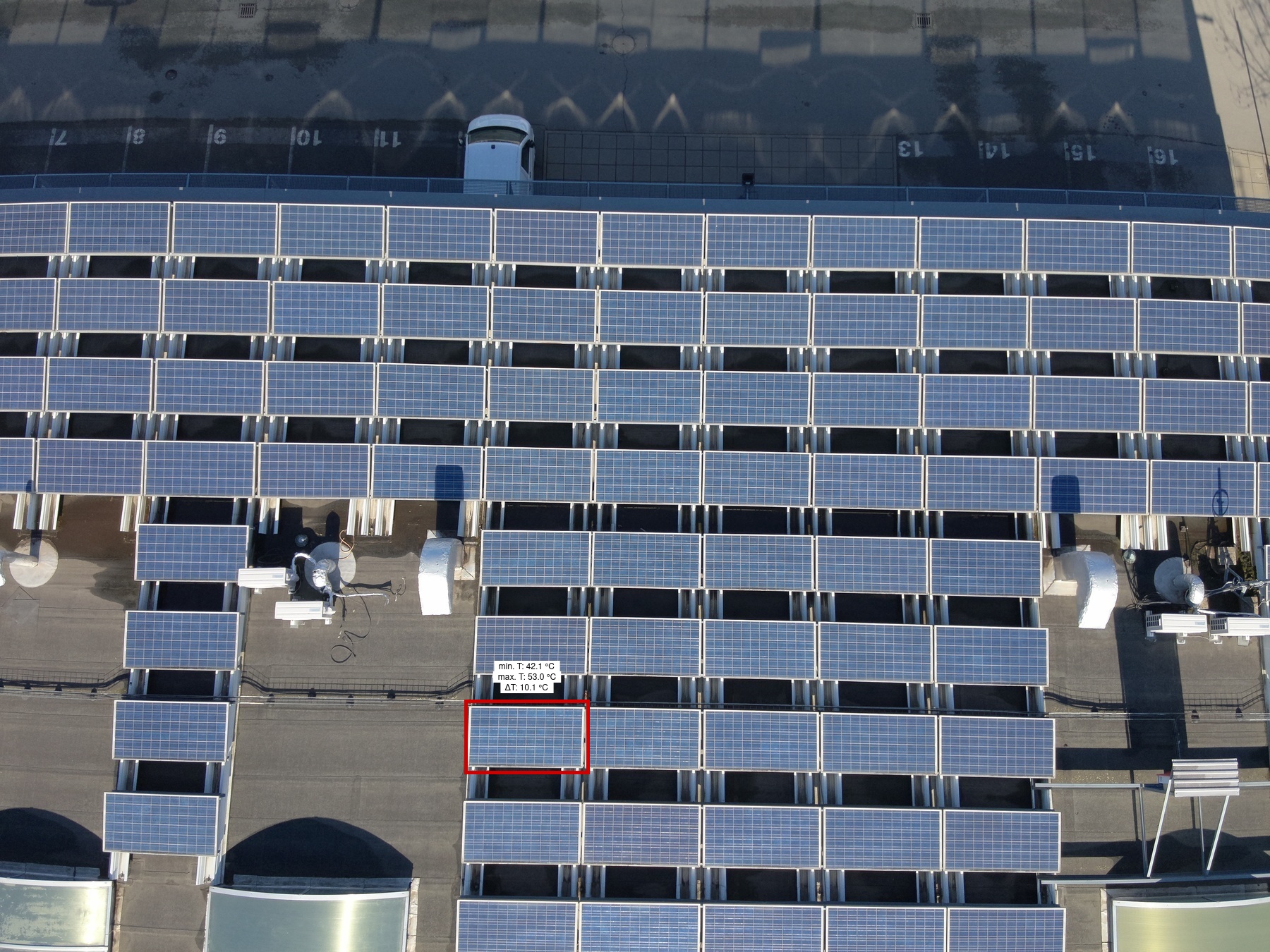
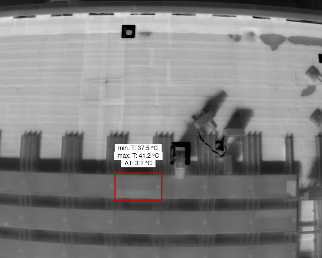
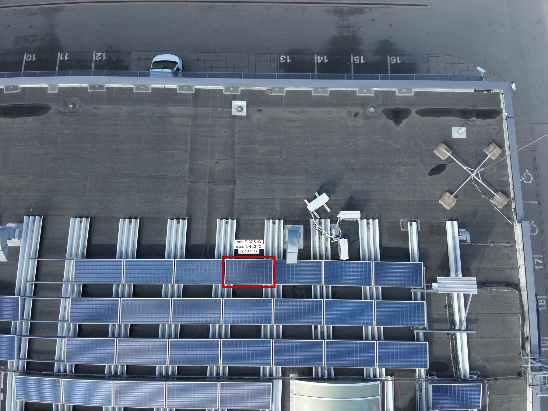
Cell Multi Medium |
1 | 39F | 1 | 1 | 1 | 1 | Low | 10.1 | |
|
|
Diode |
2 | 96C | 1 | 1 | 4 | 1 | Medium | 5.5 | |
|
|
Diode |
2 | 88C | 1 | 1 | 3 | 1 | Medium | 3.4 | |
|
|
Diode |
2 | 15B | 1 | 1 | 6 | 1 | Medium | 6.2 | |
|
|
Diode |
2 | 41C | 1 | 1 | 2 | 1 | Medium | 3.7 | |
|
|
Diode |
2 | 93A | 1 | 1 | 10 | 1 | Medium | 3.3 | |
|
|
Cell Multi Low |
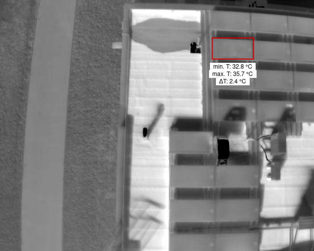
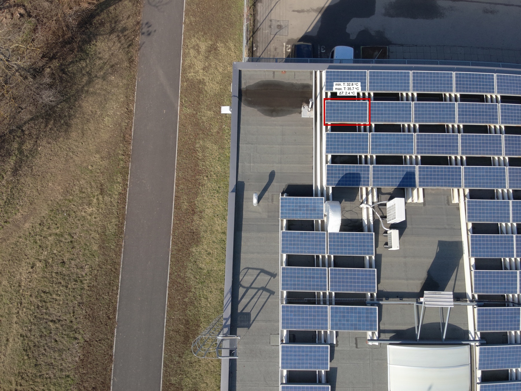
2 | 2A | 1 | 1 | 1 | 1 | Low | 2.4 | |
|
|
Diode |
2 | 11C | 1 | 1 | 1 | 1 | Medium | 3 | |
|
|
Diode |
2 | 3D | 1 | 1 | 11 | 1 | Medium | 4.1 | |
|
|
Cell Low |
2 | 90E | 1 | 1 | 4 | 1 | Low | 2.1 | |
|
|
Diode |
2 | 73C | 1 | 1 | 1 | 1 | Medium | 4.2 | |
|
|
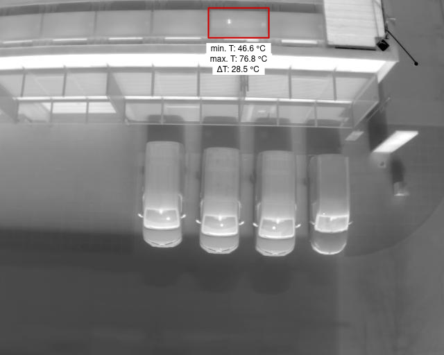
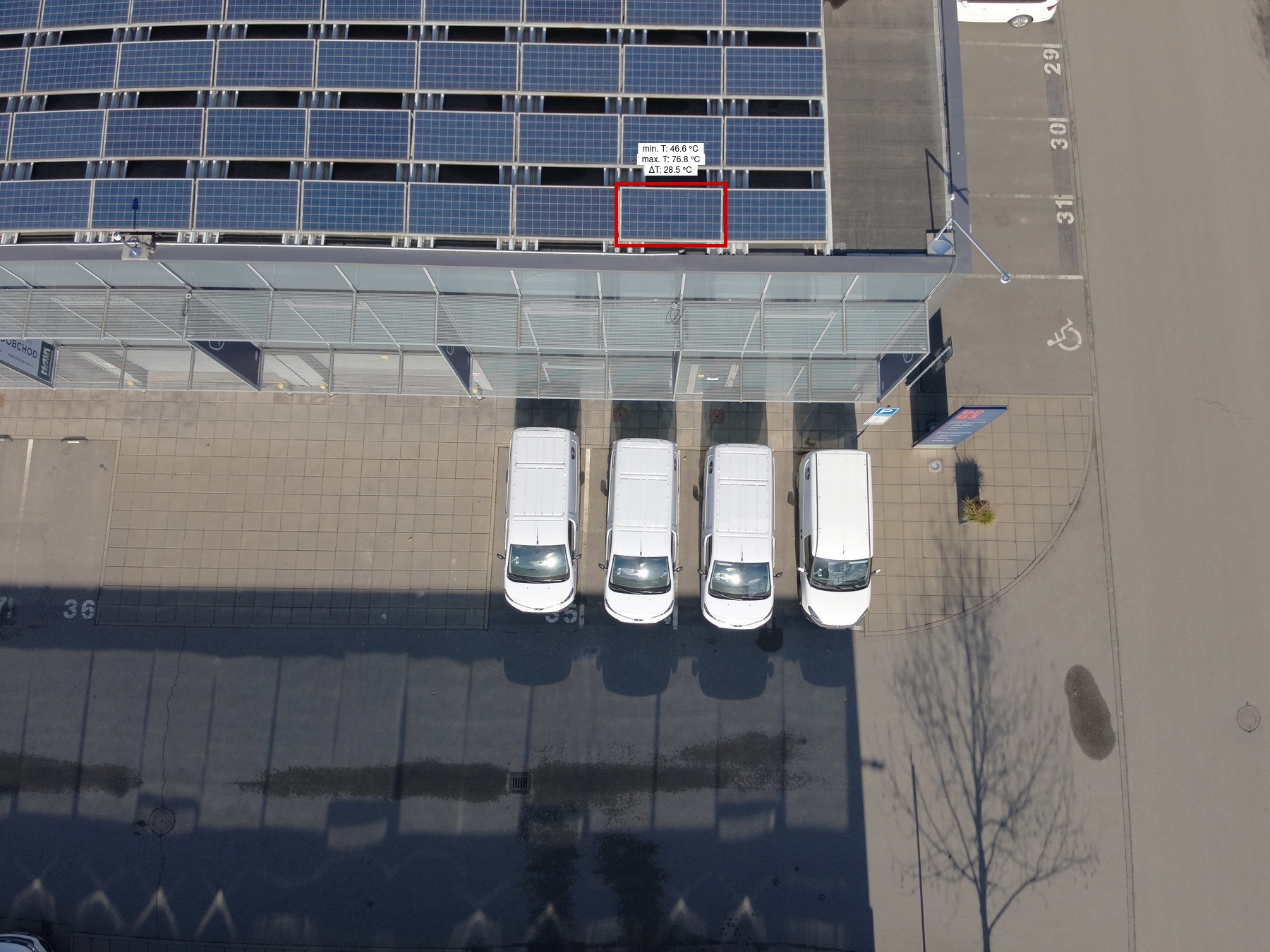
Internal Short Circuit High |
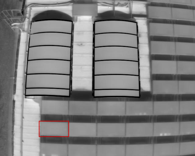
1 | 32 | 1 | 1 | 27 | 1 | Low | 28.5 | |
|
|
Diode |
2 | 80C | 1 | 1 | 7 | 1 | Medium | 6.2 | |
|
|
Diode |
2 | 73A | 1 | 1 | 2 | 1 | Medium | 3.9 | |
|
|
Diode |
2 | 38B | 1 | 1 | 5 | 1 | Medium | 3.7 | |
|
|
Diode |
2 | 74A | 1 | 1 | 2 | 1 | Medium | 3.9 | |
|
|
Cell Multi Low |
2 | 6A | 1 | 1 | 2 | 1 | Low | 5.9 | |
|
|
Diode |
2 | 18B | 1 | 1 | 13 | 1 | Medium | 4.5 | |
|
|
Diode |
2 | 71E | 1 | 1 | 7 | 1 | Medium | 3.2 | |
|
|
Diode |
2 | 64A | 1 | 1 | 12 | 1 | Medium | 6 | |
|
|
Diode |
2 | 34A | 1 | 1 | 2 | 1 | Medium | 4.5 | |
|
|
Diode |
2 | 32A | 1 | 1 | 1 | 1 | Medium | 3.9 | |
|
|
Diode |
2 | 70C | 1 | 1 | 4 | 1 | Medium | 3.1 | |
|
|
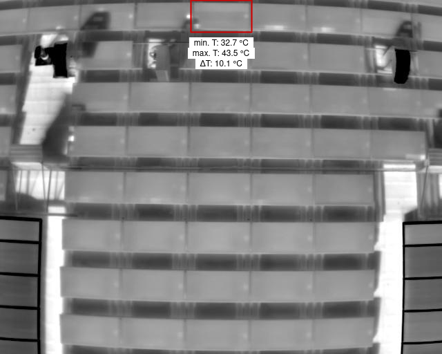
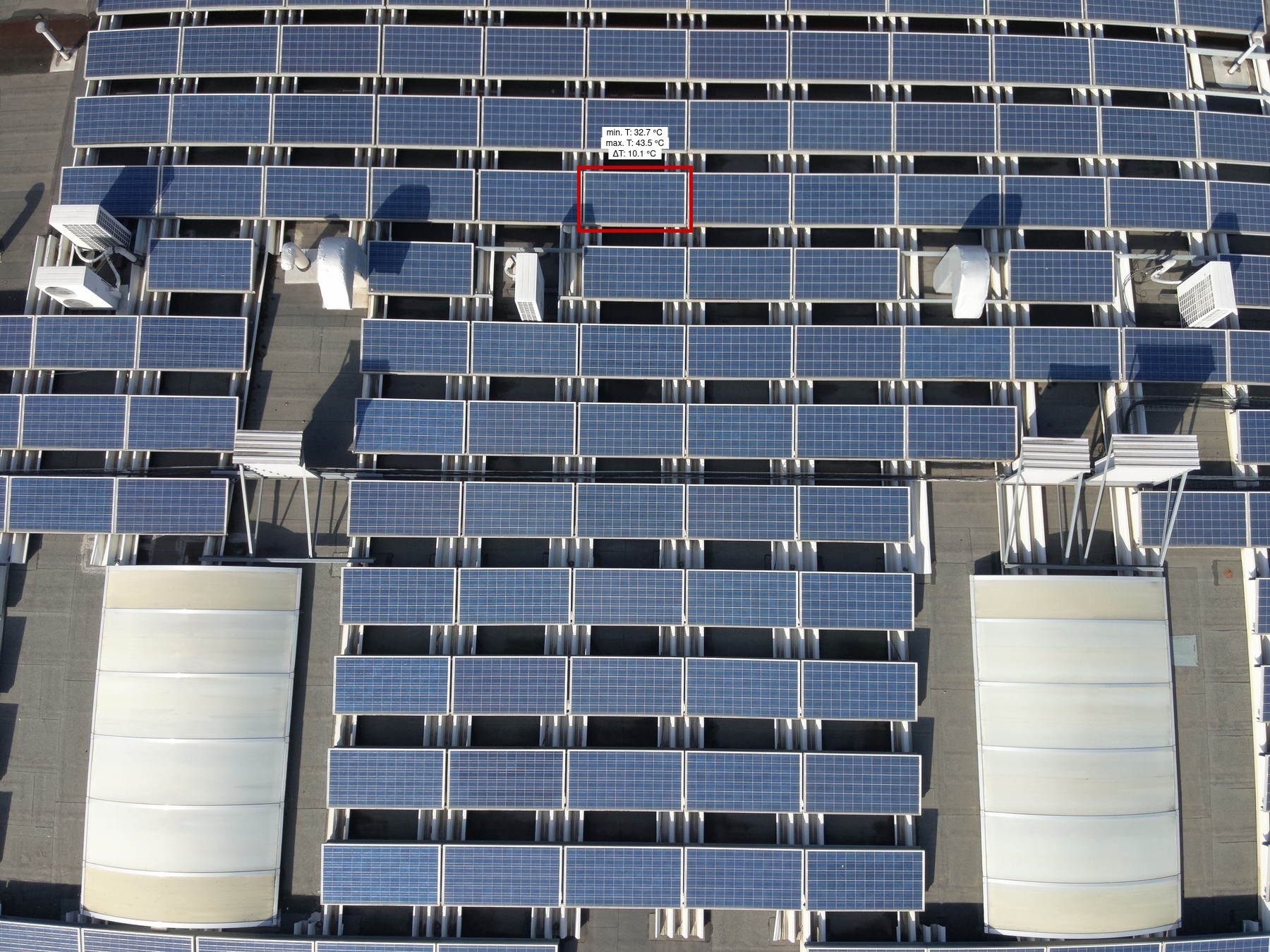
Diode |
2 | 4C | 1 | 1 | 6 | 1 | Medium | 10.1 | |
|
|
Diode |
2 | 63C | 1 | 1 | 9 | 1 | Medium | 4.4 | |
|
|
Diode |
2 | 58D | 1 | 1 | 4 | 1 | Medium | 3 | |
|
|
Diode |
1 | 30A | 1 | 1 | 1 | 1 | Medium | 3.3 | |
|
|
Soiling |
1 | 21B | 1 | 1 | 1 | 1 | Low | ||
|
|
Cracking |
2 | 51D | 1 | 1 | 1 | 1 | High | ||
|
|
Diode |
2 | 50B | 1 | 1 | 5 | 1 | Medium | 4.1 | |
|
|
Diode |
2 | 16A | 1 | 1 | 4 | 1 | Medium | 4.4 | |
|
|
Diode |
2 | 20B | 1 | 1 | 2 | 1 | Medium | 2 | |
|
|
Diode |
2 | 42B | 1 | 1 | 5 | 1 | Medium | 3.3 | |
|
|
Diode |
1 | 92E | 1 | 1 | 1 | 1 | Medium | 4.5 | |
|
|
Cell Multi Low |
2 | 47A | 1 | 1 | 1 | 1 | Low | 3.6 | |
|
|
Diode |
1 | 16D | 1 | 1 | 5 | 1 | Medium | 3.2 | |
|
|
Diode |
2 | 23D | 1 | 1 | 3 | 1 | Medium | 4.1 | |
|
|
Diode |
2 | 20A | 1 | 1 | 6 | 1 | Medium | 4.2 | |
|
|
Diode |
1 | 21C | 1 | 1 | 5 | 1 | Medium | 5.5 | |
|
|
Internal Short Circuit High |
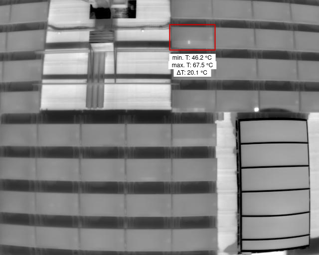
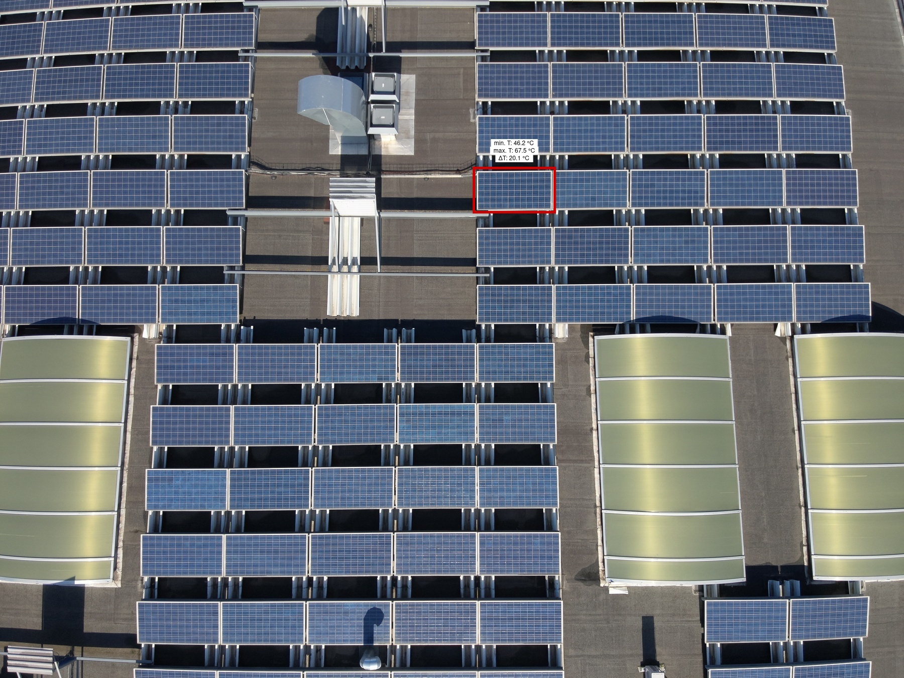
1 | 18C | 1 | 1 | 1 | 1 | Low | 20.1 | |
|
|
Diode |
2 | 21B | 1 | 1 | 4 | 1 | Medium | 3.9 | |
|
|
Diode |
2 | 42D | 1 | 1 | 3 | 1 | Medium | 4.3 | |
|

|
Diode |
2 | 31A | 1 | 1 | 5 | 1 | Medium | 4 | |
|
|
Diode |
2 | 31A | 1 | 1 | 6 | 1 | Medium | 4.8 | |
|
|
Diode |
2 | 25E | 1 | 1 | 8 | 1 | Medium | 4.4 | |
|
|
Soiling |
2 | 29A | 1 | 1 | 11 | 1 | Low | ||
|
|
Cracking |
1 | 10A | 1 | 1 | 2 | 1 | High | ||
|
|
Cell Low |
2 | 28C | 1 | 1 | 1 | 1 | Low | 2.4 | |
|
|
Cell Multi Low |
2 | 30A | 1 | 1 | 11 | 1 | Low | 3.9 |
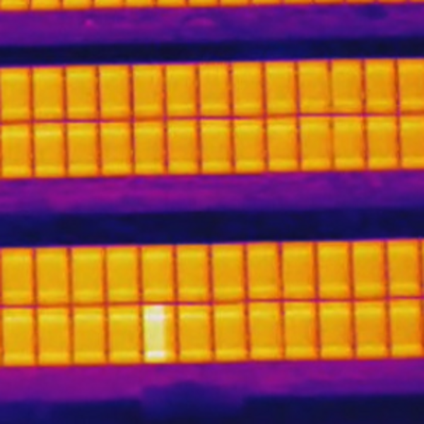
Cell MediumAnomaly where the cell temperature is higher than the surrounding area by 10–20 °C. |

Cell LowAnomaly where the cell temperature is higher than the surrounding area, but not by more than 10 °C. |
Cell Multi HighOverheating of a group of cells, where the anomaly area temperature is higher than the surrounding area by more than 20 °C. |

Cell Multi MediumOverheating of a group of cells, where the anomaly area temperature is higher than the surrounding area by 10–20 °C. |

Cell Multi LowOverheating of a group of cells, where the anomaly area temperature is higher than the surrounding area, but not by more than 10 °C. |

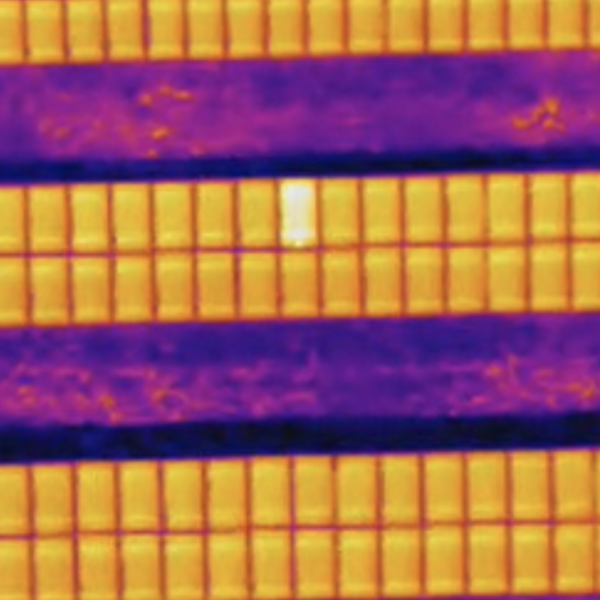
Internal Short Circuit HighMulti-cell anomaly occurring within diode boundaries, where the temperature is higher than the surrounding area by more than 20 °C. |
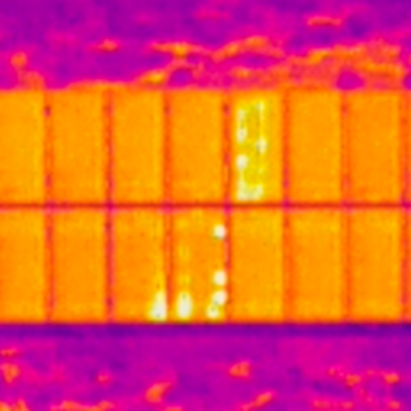
Internal Short Circuit LowMulti-cell anomaly occurring within diode boundaries, where the temperature is higher than the surrounding area, but not by more than 10 °C. |
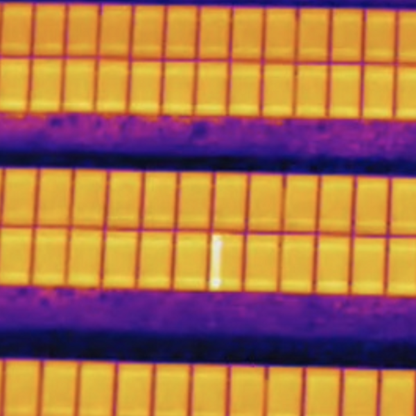
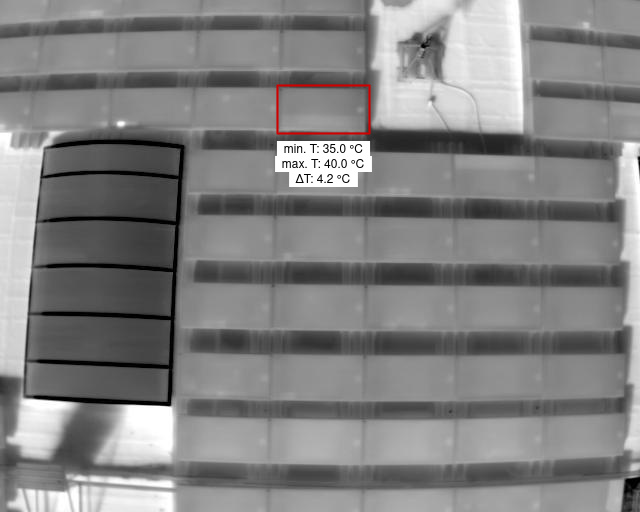
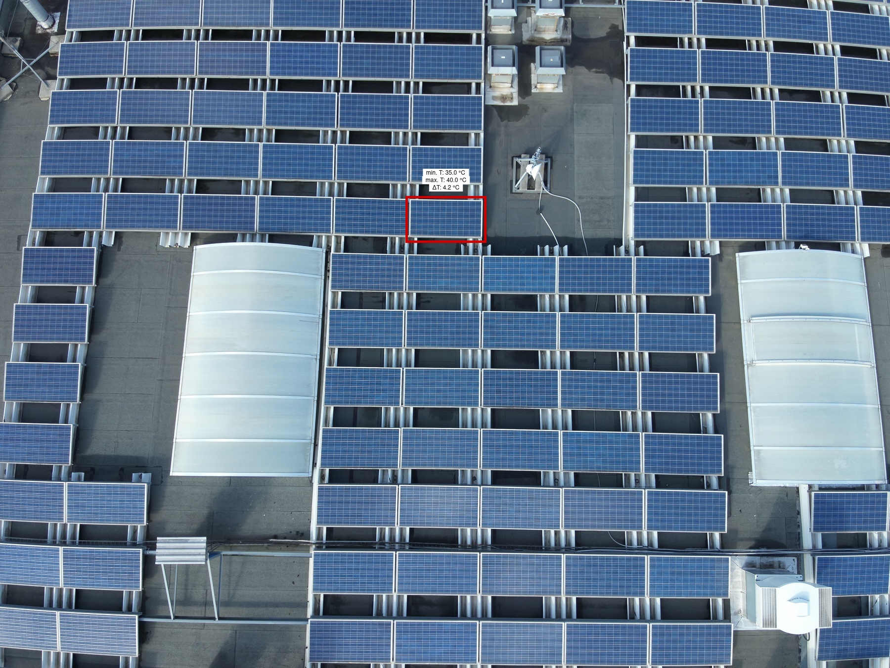
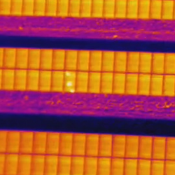
DiodeA bypass diode provides current flow around a faulty cell or module. A diode-type anomaly is indicated as a bypassed diode – typically affecting one-third of the module. |
Diode MultiMultiple activated bypass diodes – typically affecting two-thirds of the module. |
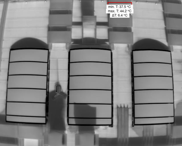
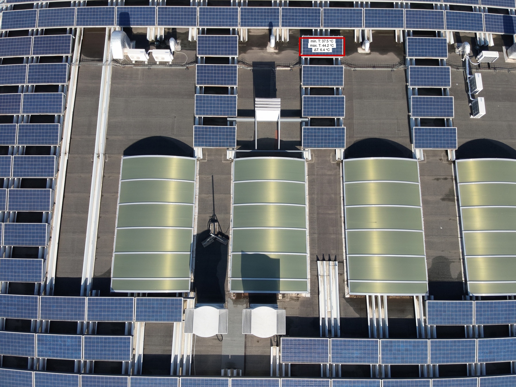
ModuleThe temperature of the entire module is high compared to the surrounding area. |
CrackingModule anomaly caused by surface cracking. |
SoilingDirt, dust, or other debris on the module surface. |